Tutorials
•
29
SUBTRACTION
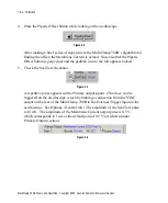
). Check the Leak Subtraction checkbox and press the button
(or use the glider to obtain a flat trace).
Figure 3.18
The optimum value is about 500 M
Ω
, the “input resistance” of the model cell.
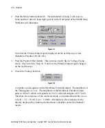
Manual adjustments of Whole Cell and Cp Fast may be necessary to perfectly
compensate the response.
Directly to the left of the Leak Subtraction button is the Output Zero button,
which provides a slightly different way of removing offsets in the Primary
Output trace. Output Zero acts like a high-pass filter, subtracting a constant DC
offset without regard to the voltage command. To illustrate its use, switch off
Leak Subtraction, and check and press Output Zero (with Holding set to a large
negative value, as described in step 3 of this Tutorial). The Primary Output
trace is baselined but unlike with Leak Subtraction, the step due to Seal Test is
not subtracted.
7. The series resistance (Rs), which typically originates near the tip of the
recording electrode, can be thought of as an unwanted resistance that is
interposed between the headstage circuitry and the membrane of the cell. Since
Rs can cause serious errors in voltage clamp mode, it needs to be reduced as
much as possible. This can be done both mechanically (
e.g.
by using lower-
resistance electrodes) and electronically. Full details are given in Chapter 5,
but the following exercise gives a foretaste of electronic Rs compensation.
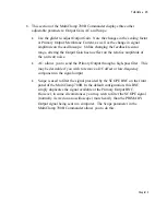
Ensure that Seal Test is running (10 mV, 100 Hz) and both Cp Fast and Whole
Cell compensation have been adjusted as at the end of step 6 above. Switch off
Output Zero and Leak Subtraction and increase Seal Test amplitude to 50 mV.
The relatively slow rise in the Primary Output current trace (~1 ms) is a
manifestation of series resistance error. The goal is to speed up this risetime
using Rs compensation.
Chapter 3


