Tutorials
•
37
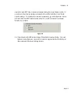
15. The Pulse button in current clamp allows you to apply single current steps of
variable amplitude and duration. Experiment with different settings for Pulse
amplitude and duration while monitoring the effect on Primary Output.
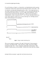
Figure 3.32
16. Switch on both Holding and Tuning features. Observe Primary Output on the
oscilloscope while pressing the I=0 button.
Figure 3.33
I=0 is a special mode of current clamp in which all command inputs are
disconnected. With the model cell, the Primary Output Membrane Potential
signal returns to near 0 mV when I=0 is pressed. In a real cell the Membrane
Potential would return to the resting potential of the cell. See
IMPALING
CELLS
in Chapter 4 for detailed information on current clamp experiments
with real cells.
Tutorial 6 – Whole-Cell Configuration: Automatic Mode
Switching
1. Set up MultiClamp 700B as follows: Reset to Program Defaults, connect CELL
position of Patch-1U model cell (shielded and grounded) to CV-7 headstage.
2. Make the following changes in VC mode:
a. Click Auto Pipette Offset.
b. Turn on Seal Test (check box).
c. Click Auto Cp Fast.
Chapter 3

