84
•
Reference Section
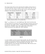
compensation. After these approximate values have been established, iterative
adjustment using
becomes easier.
Filtering the Command Stimulus
Under some conditions, such as when very large voltage clamp steps are applied,
the capacitance transients cannot be fully compensated and the amplifier may still
saturate. Under these conditions it may be helpful to reduce the size of the
capacitance transient by slowing down the voltage clamp command step. This can
be achieved by filtering the command stimulus before it is applied to the cell. This
filtering can be done within the MultiClamp 700B. (See Chapter 5,
EXTERNAL
COMMAND INPUTS
.)
Capacitance Neutralization
•
Used to partially cancel the effects of microelectrode capacitance in I-Clamp
mode.
•
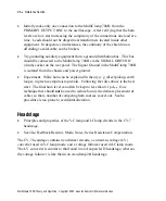
This control is adjusted in the
field in the
I-Clamp pane.
•
See also Bridge Balance.
Input Capacitance
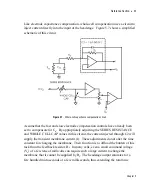
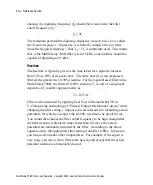
The capacitance (C
in
) at the input of the headstage amplifier is due to the
capacitance of the amplifier input itself (C
in1
) plus the capacitance to ground of the
microelectrode and any connecting lead (C
in2
). C
in
combined with the
microelectrode resistance (R
e
) acts as a low-pass filter for signals recorded at the tip
of the microelectrode. For optimal performance at high frequencies this RC time
constant must be made as small as possible.
Two techniques may be used to increase the recording bandwidth.
•
Use microelectrodes with the lowest possible resistance compatible with stable
recording, and take steps to minimize the contribution to C
in
by the capacitance
MultiClamp 700B Theory and Operation, Copyright 2005 Axon Instruments / Molecular Devices


