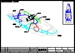
background image

Project rev.

Sheet rev.

Drawing by

Date

Modified by

Description

A

B

C

D

E

F

1

2

3

4

5

6

7

8

Date of modification

Sheet

Loc

HL

/

Project ID

Boat

Boat model

Product code

Copyright by

Sub-product code

Title

1

2

3

4

5

6

7

8

A

B

C

D

E

F

58

22

Axopar

A1: INTRODUCED DRAWING.

TuM

9.6.2020

TuM

1

A

9.6.2020

18

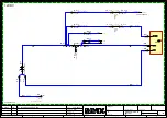
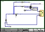
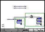
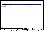
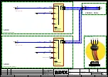
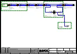
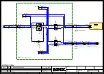
DIAGRAM -
NAVIGATION EQ.

/12.A7

/12.D7

1

2

23804

-F

.4

3A

AIC: 2500A

PLOTTER 1

1

-F4

2

-F4

MA

1

2

23804

-F

.5

3A

AIC: 2500A

PLOTTER 2

1

-F5

2

-F5

INPUT+

4/8

2635810

-BS_X2b

5/8

2635810

-BS_X2b

1

2

23804

-F

.6-

3A

AIC: 2500A

PLOTTER 1

1

-F6-

2

-F6-

MA

4/8

2635810

-EX_X2b

1

2

23804

-F

.7-

3A

AIC: 2500A

PLOTTER 2

1

-F7-

2

-F7-

INPUT+

5/8

2635810

-EX_X2b

4/8
2634810

-X.2b

5/8

2634810

-X.2b

-A.1

PLOTTER 1

Power: 30W

+/2

-A1

-/2

-A1

-A.2

PLOTTER 2

Power: 30W

+/2

-A2

-/2

-A2

-XG:1b

15318

DECK H. INPUT-

1/1

KR5

-XG1b-1

EXTENDED PACKAGE

EXTENDED PACKAGE

BASIC PACKAGE

BASIC PACKAGE

CONSOLE AREA

CONSOLE AREA

12VDC

2.5 RED

PL

2.5 RED

PL

2.5 RED

PL

2.5 RED

PL

2.5 RED

PLOTTER_1

2.5 RED

PLOTTER_2

2.5 BLACK

INPUT-

2.5 BLACK

INPUT-

6 RED

6 RED

Summary of Contents for 22 SPYDER

Page 1: ...OWNER S MANUAL AXOPAR 22 SPYDER ...

Page 2: ... 2 3 Life raft 8 3 Product overview 9 3 1 Purpose of use 9 3 2 Identification 9 3 3 Builder s plate 9 3 4 CE certification 10 3 5 Conformity 10 3 6 Dimensions and weight 12 3 7 Boat layout 13 4 Product description 15 4 1 Stability and buoyancy 15 4 1 1 Self draining systems 15 4 1 2 Openings in the hull and deck 16 4 1 3 Bilge system 18 4 2 Technical systems 20 4 2 1 Electrical system 20 4 2 2 12 ...

Page 3: ...ring maintenance 38 6 1 4 Starting the engine 38 6 2 Swivel seat Driver and passenger seats 38 6 3 Inspecting the boat 39 6 3 1 Checklist Regular inspection before leaving harbor 39 6 3 2 Checklist After using the boat 40 6 4 Handling the boat 40 6 4 1 Checklist Boat handling before leaving harbor 40 6 4 2 Leaving the jetty 41 6 4 3 Driving the boat 41 6 4 3 1 Dead man s switch 42 6 4 3 2 Driving ...

Page 4: ...ing 50 7 7 2 Scratches and nicks 51 7 7 3 Stains 51 7 7 4 Deep marks gouges and holes 51 8 Environment 52 8 1 Requirements for North America 52 9 Appendix I Checklists 53 9 1 Checklist Fire in the engine 53 9 2 Checklist After fire 53 9 3 Checklist Regular inspection before leaving harbor 53 9 4 Checklist After using the boat 54 9 5 Checklist Boat handling before leaving harbor 54 9 6 Checklist Be...

Page 5: ...d trained workshops Changes that can affect the boat s security features must be assessed carried out and documented by competent professionals The boat manufacturer cannot be held responsible for unauthorized modifications Every change to the boat s center of gravity from highly mounted heavy equipment or a new engine type etc will significantly affect the stability trim and performance of the bo...

Page 6: ...material also contains confidential information which may not be disclosed to others without the prior written consent of Axopar Boats 1 5 Disclaimer The material in this manual is for information purposes only Axopar Boats reserves the right to change the products without prior notice to improve reliability function design or other characteristics of the products Axopar Boats assumes no liability...

Page 7: ...nd distribute loads appropriately to maintain design trim Avoid placing heavy equipment or material high up in the boat The liquids in the built in tanks are not included in the maximum load shown on the builder s plate WARNING Do not exceed the maximum number of persons allowed in the boat The total weight of the persons on board and their personal luggage must never exceed the maximum load of th...

Page 8: ...ncy exits Never block access to safety equipment such as fuel valves or main power switches Never block access to fire extinguishers visible or concealed Never modify the boat s systems especially electrical fuel or gas systems In case of fire use the fire extinguisher on the boat See the section Safety diagram for the exact location of the fire extinguisher If the fire starts to get out of contro...

Page 9: ...xtinguishing Put out possible smoldering fires with water 2 2 4 Checklist After fire Open doors and windows for better ventilation Inspect the boat and its equipment and repair eventual damages Contact local authorities if needed Make sure that the fire extinguishing equipment is refilled or replaced after use 2 3 Life raft The boat is not equipped with a life raft by the manufacturer Storing a li...

Page 10: ...xample FI AXO2A001F920 Data FI Country of manufacturer Finland Hyphen AXO Manufacturer Axopar 2A Boat model A Spyder 001 Boat number F Manufacturing month A January B February C March etc 9 Last digit of the manufacturing year 20 Model year 3 3 Builder s plate The builder s plate is always fitted close to the steering position in the boat DNV GL has inspected that the boat fulfills the Recreationa...

Page 11: ... requirements stated Category Description A Ocean The boat is designed for extended voyages where conditions experienced may exceed wind force 8 on Beaufort Scale and include significant wave heights of at least 4 meters Under such conditions the boat must be largely self sufficient B Offshore The boat is designed for offshore voyages where conditions up to and including wind force 8 on Beaufort S...

Page 12: ...ing Structure ISO 12215 5 2008 A1 2014 ISO 12215 6 2008 Hydrostatics Stability and freeboard EN ISO 12217 1 2017 Buoyancy and floatation EN ISO 12217 1 2017 Manufacturer s maximum recommended load EN ISO 14946 2001 AC 2005 Openings in hull deck and superstructure EN ISO 9093 1 2018 EN ISO 9093 2 2018 EN ISO 12216 2018 Flooding EN ISO 11812 2018 EN ISO 15083 2018 ISO 8849 2018 Handling characterist...

Page 13: ...load excluding engine 0 85 m 2 ft 9 in Height measured from waterline at light load without portable navigation light 1 5 m 4 ft 11 in Power SI units US units Maximum recommended engine power 1 x 149 kW 1 x 200 hp Weight and loading SI units US units Hull weight excluding engine 1100 kg 2425 lb Category C Maximum number of persons Default weights Adult 75 kg 165 lb Child 37 5 kg 83 lb 7 Axopar 22 ...

Page 14: ...Tank capacity SI units US units Fuel tank 230 l 61 gal Fresh water tank 32 l 8 gal Septic tank 25 l 7 gal The boat s stability assessment is based on maximum load conditions The maximum recommended load only contains the weight components mentioned above 3 7 Boat layout The boat has several deck options The layout of the equipment and the technical components may vary depending on the chosen acces...

Page 15: ... Multi storage compartment In the front part of the cockpit there is a separate storage room toilet option with a door that opens to the front deck 1 Storage room toilet option Axopar 22 Spyder Document ID 22S202103EN Owner s Manual 2021 Axopar Boats Page 14 ...

Page 16: ...or the toilet s flushing water 4 1 1 Self draining systems The boat is equipped with self draining systems for the whole deck area The system is drained through drain holes in the aft of the boat There are drain holes for water in both aft corners of the deck The openings are directly connected to the sea The deck of the boat has been designed to allow the water to drain straight into the sea via ...

Page 17: ...ck There are several inlets through the boat that include valves for opening and closing such inlets It is recommended to keep these inlets closed if the boat is out of use for a long time and to open them again when the boat is used again If the boat is lifted out from water or in rainy conditions inlets should be kept open Always check that all hatches are securely closed before and after using ...

Page 18: ...manned 1 Inspection hatch in the engine bracket 2 Floor hatch or multistorage roof hatch 3 Console door 4 Storage box hatches 5 Front storage box The location and number of these components depend on the level of the equipment on the boat Axopar 22 Spyder Document ID 22S202103EN Owner s Manual 2021 Axopar Boats Page 17 ...

Page 19: ...d with a float which triggers them automatically if there is water in the bilge space The pumps can also be controlled manually from the switches on the steering console The manual bilge pump is controlled with its handle which is located in the aft sofa aft of multistorage The purpose of the manual bilge pump is to drain the aft bilge room The electrical pumps are submersible One of them is locat...

Page 20: ...rea of each pump respectively CAUTION Do not run dry for long time The pump will be damaged WARNING Check the functionality of the bilge pumps regularly by manually activating them Remove any waste from the intakes The combined capacity of the bilge system is not designed to pump out the boat in the event of hull damage The pumps are by default in the automatic mode and pump out the bilge once the...

Page 21: ...aunching that the inlets through the side and bottom are tightly closed 1 Waste water outlet 2 Transducer 4 2 Technical systems 4 2 1 Electrical system WARNING Risks of fire explosion and electric shock Improper use of the electric DC system may result in fire or explosion Follow the instructions carefully Axopar 22 Spyder Document ID 22S202103EN Owner s Manual 2021 Axopar Boats Page 20 ...

Page 22: ...r switch off the main switch when the engine is running because this may cause damage to the alternator Never carry out electrical installations when the power is switched on Never modify the boat s electrical system or diagrams service and maintenance must be carried out by a qualified electrician Never modify the nominal rated amperage of the overvoltage protector Never install or replace electr...

Page 23: ...all main switches Devices that constantly need current are active regardless of the position of the main switches The base drawing of the boat s electrical system is presented in the Appendix II The main switch is located under aft seat In the main switch panel are direct supply switches for critical equipment and main switches for the start batteries the service battery and the Aux battery Curren...

Page 24: ...that need current when main switches are turned off When pushed down the switch is on and when pushed up it is off The switch indicates a short circuit or interference in the electronic circuit by springing up to the off position The switch can be reconnected by pushing it back down to the on position Do not reconnect the switch before you have found out the reason for the interference Axopar 22 S...

Page 25: ...2 5 Fuses The fuse panel includes fuses for the boat s equipment The fuse panel is located in the toilet room The fuses are in the form of trip switches that break the circuit and spring up when tripped Do not reset the switch before you have found out the reason for the breaker tripping After that press the switch back down The panel has a combined switch and fuse for the macerator and the fresh ...

Page 26: ...he metal strip is damaged contact a qualified nautical electrician If it is necessary to open the cover make sure that all the current cables from the batteries are disconnected 4 2 7 Batteries The standard boat is equipped with a start battery only and a service battery is optional dual battery system The dual battery system has been designed and built so that the boat s engine starts even if its...

Page 27: ...partially discharged battery can freeze and crack Always disconnect the cable terminals from the battery to avoid oxidation When removing batteries disconnect the negative pole first and make sure that there are no flammable or explosive materials or liquids nearby When putting the batteries back in place connect them in reverse order positive pole first 4 2 7 3 Cleaning the batteries The top of t...

Page 28: ...oat If the boat has optional decking material wet down the deck with water before refueling This ensures that any fuel spillage will float on the water and not penetrate the decking material Water reaching the engine s injection system can cause rapid corrosion damage to the precision components in the injection pump components For this reason it is vital to check the extra fuel filter regularly f...

Page 29: ... equipped with a water supply point in the toilet and in the deck shower The tank is located under aft deck The pump is integrated in the tank The fresh water tank is filled via the inlet pipe on the aft foredeck The fresh water system is turned on by switching on the fresh water pump The pump switch is located on the fuse panel The system maintains a working pressure automatically which is why th...

Page 30: ...ic system The boat s septic system consists of the toilet seat the septic tank and the related systems 1 Toilet seat 2 Septic tank 3 Septic macerator 4 Toilet flush water inlet and septic tank seacock 5 Toilet seat pump 6 Septic tank suction fitting Axopar 22 Spyder Document ID 22S202103EN Owner s Manual 2021 Axopar Boats Page 29 ...

Page 31: ...or chlorine nor corrosive or petroleum based agents These materials can damage the plastic and rubber parts in the toilet Lubricate the pump shaft with Vaseline to increase the service life of the seal Flush the toilet system thoroughly with fresh water when the boat is not in use 4 3 2 2 Septic tank Avoid environmental pollution The black water tank is fitted with a deck outlet pump using an inte...

Page 32: ...water The whole system must be thoroughly drained of water when the boat is lifted out of the water This measure prevents frost damage bacteria growth and smells We do not recommend the use of antifreeze since it is impossible to guarantee that it reaches all parts of the system Axopar 22 Spyder Document ID 22S202103EN Owner s Manual 2021 Axopar Boats Page 31 ...

Page 33: ...ed to be adjusted depending on how the boat is loaded CAUTION Note the location of the log transducer to avoid damaging it Protect the hull sides well to avoid damages The lifting beam should be exactly the same width as the boat Always take great precautions near and around the boat when lifting The location of the lift straps is indicated in the figure Before operating any lifting equipment Chec...

Page 34: ...are sufficient to carry the boat and its engine equipment battery boating accessories and fuel on board WARNING A boat trailer that does not have sufficient capacity or that is poorly maintained can become damaged and cause a danger on the road Make sure that the trailer capacity is sufficient to also carry the weight of the engine fuel and equipment CAUTION The hull of the boat can be damaged if ...

Page 35: ...her similar top or cover on the boat during trailering These hoods and covers can become detached at high speeds and damage the boat and cause a danger to traffic A hood or other cover flapping in the wind during trailering can damage the boat surface Keep the hood in its dedicated storage compartment during trailering or remove the hood completely if necessary Axopar 22 Spyder Document ID 22S2021...

Page 36: ...at may differ from the equipment used in the figures in this manual This might be due to any optional equipment chosen or modifications made after producing this manual In such cases we recommend that you contact your local dealer for additional information regarding the operation of the equipment in question Always maintain the boat properly and make allowance for the deterioration that will occu...

Page 37: ...e remote control 4 USB charging port 5 Trim tabs joystick 6 Theft deterrent system TDS 7 Audio system remote control 8 Key switch 9 Diagnostic port 10 Lanyard stop switch Axopar 22 Spyder Document ID 22S202103EN Owner s Manual 2021 Axopar Boats Page 36 ...

Page 38: ...Underwater lights 4 Horn 5 Bilge pump 6 Panel lights 7 Aux 6 1 3 Steering system 6 1 3 1 Checking and topping up oil Effective and properly working steering is crucial for the safety of the boat Hydraulic oil is added to the steering system via the filling plug in the steering wheel pump Axopar 22 Spyder Document ID 22S202103EN Owner s Manual 2021 Axopar Boats Page 37 ...

Page 39: ...re at idling speed Never rev up a cold engine DANGER Risk of carbon monoxide poisoning Be aware of the risks with engine exhausts For example under turbulence or disadvantageous wind conditions exhaust can enter the boat If this happens avoid idling the engines If these problems occur under way do not open the hatches and ventilators as it can worsen the problems Instead you may try solving the pr...

Page 40: ...before boat speed exceed 5 knots 6 3 Inspecting the boat Due to safety reasons the below listed inspections must be carried out before and after using the boat 6 3 1 Checklist Regular inspection before leaving harbor Safety Make sure that All the people onboard have life jackets The wind and wave conditions do not exceed the design category of the boat The dead man s switch is switched to driver T...

Page 41: ...n board The tank should always be kept at least 20 full 6 3 2 Checklist After using the boat Make sure that The main switches are switched off The septic tank discharge valve is closed There is no water in the bilge The bilge pumps are functional The deck draining works properly and all the draining valves are open All deck hatches roof canvas and doors are tightly closed 6 4 Handling the boat 6 4...

Page 42: ...n The boat will swing out from the jetty astern As the bow will move against the jetty fend off properly With only one engine this can be a little more challenging especially if the wind is pressing the boat firmly against the jetty you have to use a spring to get the stern out Firmly fend off the bow from the jetty Take a line from the bow around a bollard or cleat so that it can be easily let go...

Page 43: ...d wake as a matter of courtesy and also for the safety of yourself and others Observe and obey speed limits and prohibitions associated with a swell Follow the rules of navigation and the requirements of COLREG Convention on the International Regulations for Preventing Collisions at Sea Always make sure that you have the space needed for avoiding collisions and coming to a halt and for evasive man...

Page 44: ...ng sea Avoid crashing through waves maintain low speed If necessary deploy the sea anchor to reduce speed Planing boats can be particularly exposed in rough following seas The stern of the boat rises and the rudder does not answer so the boat broaches while the bow cuts down into the sea 6 4 3 4 Maneuvering in narrow channels When maneuvering the boat in narrow channels the engine speed should be ...

Page 45: ...o give good performance However trim tabs are a very useful aid when used correctly There are two situations in particular where the trim tabs should be used When it is desirable to trim the bow down in a rising sea and at speeds between going up planing and cruising speed When running with a strong beam wind A planing boat always leans into a strong side wind This reduces the boat s seakeeping qu...

Page 46: ...from the water Keep the gates in the flat afterdeck area closed while the boat is under way Staying on deck Staying on the working deck is not allowed for safety reasons in speeds exceeding 30 knots If the sun deck cushions or the fore deck table are in place observe the maximum speed of 15 knots to avoid the cushions or table detaching at speed or in high waves DANGER A revolving propeller is lif...

Page 47: ...ow being blown off towards other boats or the jetty Instead try to maneuver the boat so that the wind comes directly from astern Then the boat can be maneuvered straight ahead since the wind helps hold the boat on a straight course It is good to have someone on the foredeck that can go ashore and quickly turn the bow in the desired direction after the boat has stopped completely Try to always avoi...

Page 48: ...ys fix the anchor in such a way that it is securely fastened onto the boat An anchor that falls off when under way may cause serious damage to the boat and mortal danger to the crew 6 6 4 Towing and mooring CAUTION When towing another boat or being towed always drive slowly If the boat you are towing is of the displacement hull type never exceed its hull speed Always attach the tow line so that it...

Page 49: ...ish Only use wax recommended for fiberglass and follow the instructions carefully NOTICE Never wax a gelcoat surface in direct sunlight 7 2 Maintaining the interiors 7 2 1 Plastic and painted surfaces 1 Wet the surface evenly with water before the actual cleaning 2 Remove stains Remove regular stains with a brush and a lightly diluted cleaner Remove grease with a brush or a sponge and window clean...

Page 50: ...vinegar in the final rinsing water to neutralize the soap residues 5 Hang the cover to drip dry 7 4 Preventing frost damage The bilge pump system is fitted with a water lock on the hose Detach the hose and fully drain the water from the water lock and run the pumps dry Otherwise the pumps may freeze and break Unscrew the frost plug on the underside of the shower fittings If there is no frost plug ...

Page 51: ...olishing 5 Paint the bottom with antifouling paint 6 If the batteries have been removed put them back and check the electrolyte level in the cells Check the condition of the batteries 7 Check all cables clamps engine mountings and other fastenings 8 Check the steering before launching 9 Check the instrumentation 10 Close all water drain plugs 11 Check that the seacocks are tight and in order check...

Page 52: ... followed by a mild detergent If these solvents are not effective try a rubbing compound or fine sanding followed by waxing 7 7 4 Deep marks gouges and holes Deep marks gouges and holes should be repaired professionally Gelcoats can be well repaired by professionals and in most cases the repair will be undetectable NOTICE In cases where the damage has pierced the gelcoat layer further exposure to ...

Page 53: ...rself with the international regulations on the prevention of marine pollution MARPOL and comply with these regulations as far as possible 8 1 Requirements for North America The EPA standards state that in freshwater lakes freshwater reservoirs or other freshwater impoundments whose inlets or outlets are such as to prevent the ingress or egress by vessel traffic subject to this regulation or in ri...

Page 54: ...nd windows for better ventilation Inspect the boat and its equipment and repair eventual damages Contact local authorities if needed Make sure that the fire extinguishing equipment is refilled or replaced after use 9 3 Checklist Regular inspection before leaving harbor Safety Make sure that All the people onboard have life jackets The wind and wave conditions do not exceed the design category of t...

Page 55: ...ll 9 4 Checklist After using the boat Make sure that The main switches are switched off The septic tank discharge valve is closed There is no water in the bilge The bilge pumps are functional The deck draining works properly and all the draining valves are open All deck hatches roof canvas and doors are tightly closed 9 5 Checklist Boat handling before leaving harbor For safe navigation under all ...

Page 56: ...nditions and make sure that there is good holding ground 5 Check that the safety chain has been released from the anchor 6 Wait until you have reached the intended anchoring point before lowering the anchor 7 Let out the anchor line equal to at least three times the depth of the water 8 Put the engine in astern to check that the anchor has taken hold only when bow anchoring 9 Note your position on...

Page 57: ...urface gelcoat has lost its shine use a rubbing compound on these areas before polishing 5 Paint the bottom with antifouling paint 6 If the batteries have been removed put them back and check the electrolyte level in the cells Check the condition of the batteries 7 Check all cables clamps engine mountings and other fastenings 8 Check the steering before launching 9 Check the instrumentation 10 Clo...

Page 58: ...10 Appendix II Fuel system 10 Appendix II Fuel system Axopar 22 Spyder Document ID 22S202103EN Owner s Manual 2021 Axopar Boats Page 57 ...

Page 59: ......

Page 60: ...11 Appendix III Electrical diagrams 11 Appendix III Electrical diagrams Axopar 22 Spyder Document ID 22S202103EN Owner s Manual 2021 Axopar Boats Page 58 ...

Page 61: ... product code Title 1 2 3 4 5 6 7 8 A B C D E F 58 22 Axopar A1 INTRODUCED DRAWING TuM 11 5 2020 TuM 1 A 11 5 2020 1 COVER ELECTRICAL DIAGRAM PRODUCTION DRAWINGS DOCUMENT INCLUDES BOAT HARNESS PANEL GENERAL LAYOUT ELECTRICAL STRUCTURE OF 12V DC SYSTEM EURO USA 12V DC DIAGRAM 230V AC DIAGRAM PRODUCTION DRAWINGS NOTE ALL CABLE AREAS ARE IN METRIC SYSTEM mm2 Axopar 22 25 REVISION A1 ...

Page 62: ... 32633 DUAL BATTERY CABLES EXTENDED 32634 WINCH CABLES 32635 BOW THRUSTER CABLES OPTIONAL ONLY IN Ax25 OR OR 32626 SWITCH PANEL EXTENDED OR X 1 BS_X1 EX_X1 X 3 X 2 BS_X2 EX_X2 BS_X3 EX_X3 X 4 X4 OR S_XG1 S_XG1 32817 CHARGER CABLES BASIC 32816 CHARGER CABLES EXTENDED OR OPTIONAL OPTIONAL NOT DEFINED OPTIONAL ONLY IN Ax25 NOT DEFINED NOTE CONNECTOR NAME LIKE X3 IS HEADER ONLY FOR EXAMPLE X3 CONNECTO...

Page 63: ...TuM 1 A 11 5 2020 3 HARNESS LAYOUT WITH LONG CONSOLE LONG CONSOLE HARNESS PANEL GENERAL LAYOUT NOTE LAYOUT GIVES ONLY APPROXIMATE LOCATION OF PANEL AND HARNESS TOP VIEW DECK HARNESS AUDIO PACKAGE HARNESS VAC SHORE POWER UNIT VAC GALVANIC ISOLATOR VAC DECK CONTACT SOCKET VAC SOCKET OUTLET VAC CHARGER 12VDC ALTERNATOR SPLITTER ISOLATOR 12VDC MAIN SW UNIT MAIN DC NEG POINT BUSBAR AFT TECH SPACE CONSO...

Page 64: ...TuM 1 A 11 5 2020 4 HARNESS LAYOUT WITH LONG CONSOLE LONG CONSOLE HARNESS PANEL GENERAL LAYOUT NOTE LAYOUT GIVES ONLY APPROXIMATE LOCATION OF PANEL AND HARNESS SIDE VIEW VAC SHORE POWER UNIT VAC GALVANIC ISOLATOR VAC DECK CONTACT SOCKET VAC SOCKET OUTLET VAC CHARGER 12VDC ALTERNATOR SPLITTER ISOLATOR 12VDC MAIN SW UNIT MAIN DC NEG POINT BUSBAR AFT TECH SPACE CONSOLE AREA 12VDC SWITCH PANEL 12VDC F...

Page 65: ...8 Date of modification Sheet Loc HL Project ID Boat Boat model Product code Copyright by Sub product code Title 1 2 3 4 5 6 7 8 A B C D E F 58 22 Axopar 9 7 2020 TuM A 5 DECK HARNESS LAYOUT DECK HARNESS LAYOUT PORT AFT STB FWD 0 015 STB AFT FWD PORT POINT A POINT B POINT C POINT E POINT D ...

Page 66: ...8 Date of modification Sheet Loc HL Project ID Boat Boat model Product code Copyright by Sub product code Title 1 2 3 4 5 6 7 8 A B C D E F 58 22 Axopar A1 INTRODUCED DRAWING TuM 9 7 2020 TuM 1 A 10 7 2020 6 AUDIO HARNESS LAYOUT AUDIO HARNESS LAYOUT PORT AFT STB FWD 0 015 STB AFT PORT FWD ...

Page 67: ... M_S1 275A 1250A START MAIN SW G1 START BATTERY 1 1 50 10 G1a 1 1 50 10 M_S1a M_S1c 1 1 ERF2 10 M_S1d 1 1 50 10 M_S1b M 5 ENGINE 1 1 50 8 M5c 1 1 50 10 M5a 1 1 50 10 M5b INPUT INPUT DIRECT 1 1 50 10 M_S1e 1 2 20009 CH_F 1 50A CHR FUSE START 1 1 16 8 CH_F1a 1 1 16 8 CH_F1b 1 1 50 8 A_F1b BSC_START_CHR 1 1 50 8 A_F1a 1 2 13633 A_F 1 150A ALT FUSE START 1 1 50 10 G1b 1 1 50 10 G1c 1 1 16 10 M_S1f ENG...

Page 68: ...OR 22483 1 1 50 8 D1a 1 4422 02 D1e 1 1 D1f 1 1 35 6 D1b 1 1 35 6 D1c 1 1 35 6 D1d 1 2 20009 CH_F 1 50A CHR FUSE START 1 1 16 8 CH_F1a 1 1 35 8 A_F1a 1 1 16 8 CH_F1b 1 1 35 8 A_F1b ALT_SERV_ISOL EXT_START_CHR B 1 V2501 MAIN DC NEG POINT 1 1 ERF2 10 B1i IG 3 IGN KEY 1 1 4422 02 IG3 1 1 16 10 M_S1f 1 2 20010 A_F 1 100A ALT FUSE START 1 1 50 10 G1b 1 1 50 10 G1c ENGINE ENGINE ALTERNATOR EXTENDED PACK...

Page 69: ...INT 1 1 50 10 B1g 1 2 4487 M_S2 275A 1250A SERVICE MAIN SW 1 1 50 10 G2a 1 1 50 10 G2b 1 1 50 10 M_S2a 1 1 ERF2 10 M_S2d G2 SERVICE BATTERY 1 1 50 8 S_F1a 1 2 13633 S_F 1 150A SERVICE MAIN FUSE 1 1 50 8 S_F1b M_S2c DIRECT INPUT INPUT INPUT INPUT INPUT 1 1 35 10 M_S2e 1 2 20009 CH_F 2 50A CHR FUSE SERV 1 1 16 8 CH_F2a 1 1 16 8 CH_F2b 1 1 35 8 A_F2b ALT_SERV_ISOL EXT_SERV_CHR 1 1 35 8 A_F2a 1 1 16 1...

Page 70: ...of modification Sheet Loc HL Project ID Boat Boat model Product code Copyright by Sub product code Title 1 2 3 4 5 6 7 8 A B C D E F 58 22 Axopar A1 INTRODUCED DRAWING TuM 11 5 2020 TuM 1 A 11 5 2020 10 DIAGRAM BOW THRUSTER B 1 V2501 MAIN DC NEG POINT 1 1 70 10 B1e NOT DEFINED ONLY AT AX25 12VDC ...

Page 71: ...ate of modification Sheet Loc HL Project ID Boat Boat model Product code Copyright by Sub product code Title 1 2 3 4 5 6 7 8 A B C D E F 58 22 Axopar A1 INTRODUCED DRAWING TuM 14 6 2020 TuM 1 A 14 6 2020 11 DIAGRAM WINCH B 1 V2501 MAIN DC NEG POINT 1 1 25 10 B1f NOT DEFINED ONLY AT AX25 12VDC ...

Page 72: ... 2634810 X 2a 6 8 2634810 X 2a 7 8 2634810 X 2a 8 8 2634810 X 2a 1 8 2635810 BS_X2a 1 8 2635810 EX_X2a 2 8 2635810 BS_X2a 2 8 2635810 EX_X2a 3 8 2635810 EX_X2a 4 8 2635810 EX_X2a 3 8 2635810 BS_X2a 4 8 2635810 BS_X2a 5 8 2635810 EX_X2a 6 8 2635810 EX_X2a 7 8 2635810 EX_X2a 8 8 2635810 EX_X2a MAIN_1_FD MAIN_1_FD MAIN_1_FD MAIN_1_FD MAIN_2_FD MAIN_2_FD MAIN_2_FD MAIN_2_FD MAIN_3_FD MAIN_3_FD MAIN_4_...

Page 73: ...1c INPUT INPUT INPUT INPUT INPUT INPUT 11 11 2639010 X 3a 11 11 2638010 EX_X3a 11 11 2638010 BS_X3a 1 1 16 5 XG1a 1 1 16 5 XG1b XG 1a 15318 DECK H INPUT XG 1b 15318 DECK H INPUT B 1 V2501 MAIN DC NEG POINT B 1 V2501 MAIN DC NEG POINT 1 1 16 10 B1b 1 1 16 10 B1c 1 1 ERF1 25 5 XG1a 1 XG 1a 15318 DECK H INPUT 1 1 ERF1 25 4 XG1a 3 XG 1a 15318 DECK H INPUT XG 1b 15318 DECK H INPUT 1 1 KR4 XG1b 12 C NO ...

Page 74: ... 5 S_S1 5 S_S1 5 S_S1 R3K32_0 5W S_R 1 INPUT 1 11 2638010 BS_X3a 1 11 2638010 EX_X3a 1 11 2639010 X 3a 2 11 2638010 BS_X3a 2 11 2638010 EX_X3a 2 11 2639010 X 3a 10 11 BS_X3a 10 11 EX_X3a 10 11 2639010 X 3a 2 H3 2 H3 2 H2 2 H2 ANCH LT H 1 Power NAV LT PORT H 3 NAV LT STB H 2 COMPASS LT H 4 Power 2W 2 H4 2 H4 1 1 ERF1 25 4 XG1a 4 XG 1a 15318 DECK H INPUT 1 1 ERF2 4 XG1a 5 XG 1a 15318 DECK H INPUT IN...

Page 75: ... DECK LT S MID 2 H 5 Power 0 55W 2 H5 2 H5 DECK LT S AFT H 7 Power 0 55W 2 H7 2 H7 DECK LT P MID 1 H 9 Power 0 55W 2 H9 2 H9 DECK LT P MID 2 H 8 Power 0 55W 2 H8 2 H8 DECK LT P AFT H 10 Power 0 55W 2 H10 2 H10 DECK LT FWD H 11 Power 0 55W 2 H11 2 H11 XG 1b 15318 DECK H INPUT 1 1 ERF1 25 4 XG1b 9 XG 1b 15318 DECK H INPUT 1 1 ERF1 25 4 XG1b 7 XG 1b 15318 DECK H INPUT 1 1 ERF1 25 4 XG1b 8 EXTENDED PA...

Page 76: ...t by Sub product code Title 1 2 3 4 5 6 7 8 A B C D E F 58 22 Axopar A1 INTRODUCED DRAWING TuM 11 5 2020 TuM 1 A 11 5 2020 16 DIAGRAM INTERIOR LT 14 F4 1 2 23804 F 3 3A AIC 2500A INTERIOR LT 1 F3 2 F3 INPUT 2 11 2638010 EX_X2c 2 11 2639010 X 2c TOILET LT H 12 2 H12 2 H12 INPUT EXTENDED PACKAGE Power 2W 12VDC 1 5 WHITE YELLOW INT_LT 1 5 WHITE YELLOW INT_LT 1 5 BLACK INPUT ...

Page 77: ...X_X3c 3 6 2635610 EX_X3c 1 6 2634610 X 3c 3 6 2634610 X 3c 2 6 2634610 X 3c 86 87a 87 30 85 0332209150 R_K 3 12V 20 30A U W LT STB RELAY 30 5 R_K3 85 5 R_K3 86 5 R_K3 87 5 R_K3 INPUT INPUT 86 87a 87 30 85 0332209150 R_K 4 12V 20 30A U W LT PORT RELAY 30 5 R_K4 85 5 R_K4 86 5 R_K4 87 5 R_K4 INPUT UW LIGHT STB H 13 Power 30W 2 H13 2 H13 UW LIGHT PORT H 14 Power 30W 2 H14 2 H14 1 1 KR4 XG1a 10 XG 1a ...

Page 78: ...C 2500A PLOTTER 2 1 F5 2 F5 INPUT 4 8 2635810 BS_X2b 5 8 2635810 BS_X2b 1 2 23804 F 6 3A AIC 2500A PLOTTER 1 1 F6 2 F6 MAIN_2_FD 4 8 2635810 EX_X2b 1 2 23804 F 7 3A AIC 2500A PLOTTER 2 1 F7 2 F7 INPUT 5 8 2635810 EX_X2b 4 8 2634810 X 2b 5 8 2634810 X 2b A 1 PLOTTER 1 Power 30W 2 A1 2 A1 A 2 PLOTTER 2 Power 30W 2 A2 2 A2 XG 1b 15318 DECK H INPUT 1 1 KR5 XG1b 1 EXTENDED PACKAGE EXTENDED PACKAGE BASI...

Page 79: ...X2b 1 2 23806 F 8 10A AIC 2500A VHF 1 F8 2 F8 MAIN_2_FD 6 8 2635810 EX_X2b 6 8 2634810 X 2b 1 2 23804 F 7 3A AIC 2500A NMEA2000 1 F7 2 F7 MAIN_2_FD 7 8 2635810 BS_X2b 1 2 23804 F 9 3A AIC 2500A NMEA2000 1 F9 2 F9 INPUT 7 8 2635810 EX_X2b 7 8 2634810 X 2b A 5 VHF RADIO POWER 100W 2 A5 2 A5 XG 1b 15318 DECK H INPUT 1 1 KR4 XG1b 3 A 6 NMEA2000 POWER Power 36W 2 A6 2 A6 INPUT EXTENDED PACKAGE BASIC PA...

Page 80: ...S4 R3K32_0 5W S_R 4 INPUT 3 11 2638010 BS_X3a 4 11 2638010 BS_X3a 3 11 2638010 EX_X3a 4 11 2638010 EX_X3a 3 11 2639010 X 3a 4 11 2639010 X 3a 86 87a 87 30 85 0332209150 R_K 1 12V 20 30A HORN RELAY 30 5 R_K1 85 5 R_K1 86 5 R_K1 87 5 R_K1 INPUT 1 1 ERF1 25 5 XG1a 2 XG 1a 15318 DECK H INPUT HORN HN 1 2 HN1 2 HN1 1 1 ERF2 4 XG1a 12 XG 1a 15318 DECK H INPUT 1 2 23805 F 2 5A AIC 2500A HORN 1 2 23805 F 1...

Page 81: ... NO 5 S_S5 C 5 S_S5 5 S_S5 5 S_S5 R3K32_0 5W S_R 5 S_R5 INPUT 5 11 2638010 BS_X3a 6 11 2638010 BS_X3a 5 11 2638010 EX_X3a 6 11 2638010 EX_X3a 7 11 2638010 BS_X3a 7 11 2638010 EX_X3a 5 11 2639010 X 3a 6 11 2639010 X 3a 7 11 2639010 X 3a 86 87a 87 30 85 0332209150 R_K 2 12V 20 30A BILGE P RELAY 30 5 R_K2 85 5 R_K2 86 5 R_K2 87 5 R_K2 INPUT INPUT BILGE PUMP M 1 Power 36W MAN 3 M1 AUTO 3 M1 3 M1 XG 1b...

Page 82: ... 2 3 4 5 6 7 8 A B C D E F 58 22 Axopar A1 INTRODUCED DRAWING TuM 9 6 2020 TuM 1 A 9 6 2020 22 DIAGRAM FRESH W PUMP 27 E1 M 1 F20 2 F20 INPUT 10 11 2638010 EX_X2c 10 11 2639010 X 2c FRESH W PUMP M 2 Power 24W 2 M2 2 M2 XG 1b 15318 DECK H INPUT 1 1 ERF2 4 XG1b 6 1 2 2 5700 iG1 P10 DD 10A F 20 10A AIC 2000A FRESH WATER PUMP EXTENDED PACKAGE 12VDC 2 5 RED FW_PUMP 2 5 RED 2 5 RED FW_PUMP 2 5 BLACK INP...

Page 83: ...11 2638010 EX_X2c 9 11 2639010 X 2c TP_S1 TP_S2 1 4 2634410 T_X 1 2 4 2634410 T_X 1 3 4 2634410 T_X 1 1 4 2635410 T_X1 2 4 2635410 T_X1 3 4 2635410 T_X1 A 7 WC SOLENOID VALVE A7 A7 WC WASTE PUMP M 3 M3 M3 MACERATOR M 4 2 M4 2 M4 1 1 KR4 XG1a 7 XG 1a 15318 DECK H INPUT 1 1 KR4 XG1a 8 XG 1a 15318 DECK H INPUT 1 1 KR4 XG1a 6 XG 1a 15318 DECK H INPUT EXTENDED PACKAGE EXTENDED PACKAGE A B JABSCO TOILET...

Page 84: ...A9c Z1L 4 A9d Z1L 4 A9d Z1R 4 A9d Z1R 4 A9d SUBWOOFER LS 5 LS5 LS5 1 WES_6 A9a 1 WES_6 A9b XG 1b 15318 DECK H INPUT 1 1 KR4 XG1b 11 1 3 2634310 X 4 1 3 2635310 X4 2 3 2635310 X4 2 3 2634310 X 4 3 3 2635310 X4 3 3 2634310 X 4 BASIC PACKAGE EXTENDED PACKAGE EXTENDED PACKAGE BLACK GROUND BROWN MUTE ORANGE DIM BLUE AMPLIFIER ON WHITE LEFT WHITE BLACK LEFT GREY RIGHT GREY BLACK RIGHT GREEN LEFT GREEN B...

Page 85: ...DISTRIBUTION UNIT 2 A13a 2 1 1 KR4 XG1a 9 XG 1a 15318 DECK H INPUT B 1 V2501 MAIN DC NEG POINT 1 1 10024HQ B1k 1 1 4425 02 F13a EXTENDED PACKAGE DEFAULT NOT CONNECTED NOT CONNECTED V bat GND 12 24Vdc POWER STBD PORT AUTO LINE UP SECOND STATION CONNECTIONS STBD STBD PORT PORT KEY NSAF NSAF COM UP DOWN LEFT RIGHT POWER 180W I BUS IN KEY SENSE I BUS OUT NMEA200 EXT GPS USB A USB B POWER 10W CONTROL C...

Page 86: ...2639010 X 2c 9 11 2638010 EX_X1 9 11 2639010 X 1 AS212 A 15 12V DC MSU 12Vdc OUTLET A15 A15 A16 A16 AS212 A 17 12V DC COOLER BOX 12Vdc OUTLET A17 A17 1 2 23807 F 3 15A AIC 2500A 12VDC OUTLET DASH 1 2 23807 F 16 15A AIC 2500A 12VDC OUTLET DASH 1 2 23808 F 15 20A AIC 2500A 12VDC COOLER BOX B 1 V2501 MAIN DC NEG POINT 1 1 10024HQ B1d XG 1b 15318 DECK H INPUT 1 1 ERF2 5 XG1b 2 XG 1b 15318 DECK H INPUT...

Page 87: ... 10A AIC 2500A AUX 1 1 F17 2 F17 MAIN_4_FD 1 2 23806 F 10 10A AIC 2500A AUX 2 1 F10 2 F10 INPUT 1 2 23806 F 18 10A AIC 2500A AUX 2 1 F18 2 F18 INPUT C NO NC 14077 S_S 4 AUX NO 5 S_S4 C 5 S_S4 5 S_S4 5 S_S4 R3K32_0 5W S_R 4 INPUT C NO NC 14077 S_S 7 AUX NO 5 S_S7 C 5 S_S7 5 S_S7 5 S_S7 R3K32_0 5W S_R 7 INPUT S_S4in S_S4out S_S7in S_S7out INPUT NO WIRE BASIC PACKAGE EXTENDED PACKAGE NO WIRE NO WIRE ...

Page 88: ...18440 25A CHARGER B 1 V2501 MAIN DC NEG POINT 1 1 16 10 B1j BAT 1 A20d BAT_E 1 A20a BAT 1 A20d BAT_2 2 A20c BAT_E 1 A20a BAT_1 1 A20b CHARGER_L CHARGER_PE CHARGER_N 2 BAT E 3 BAT 1 4 BAT 2 AC INPUT L N PE GND DC CONNECTIONS BAT BANK 1 BAT BANK 2 BAT BANK 3 1 BAT NEGATIVE DC CONNECTIONS BACK VIEW 1 2 3 4 1 BAT 2 BAT E 3 BAT 1 4 BAT 2 2 BAT E 3 BAT 1 4 BAT 2 AC INPUT L N PE GND DC CONNECTIONS BAT BA...

Page 89: ... 10 GALVANIC ISOLATOR 30A 26895 1 1 10022HQ AC_A10c GAL ISOL SHIP PE B 1 V2501 MAIN DC NEG POINT 1 1 10024HQ B1ac MARINA SHORE POWER SOCKET 29838 SHORE POWER MLC ADAPTER 200mm 2 5mm2 L PE N 31331 O2 Deck Contact 16A 250V S S IP56 OUTSIDE THE BOAT STRUCTURE 31332 Shore Power Cable 16A 230V 25m 26895 O2 Galvanic Isolator 30A 120 240 VAC 29189 CONNECTION CABLE 200CM IP68 2 5mm2 WITH TUBE 22978 CONNEC...

Page 90: ... 2 1 WES_1 5 AC_F2b 4 1 WES_1 5 AC_F2d 1 2 3 4 GW90046 AC_F 3 10A BT CHARGER 1 1 WES_2 5 AC_F3a 1 1 WES_2 5 AC_F3c 2 1 WES_1 5 AC_F3b 4 1 WES_1 5 AC_F3d AC_L 1 LIVE BUSBAR AC_L1 AC_N 1 NEUTRAL BUSBAR AC_N1 TO SOCKET TO BT CHARGER 230VAC 50Hz 32828 Axopar 22 SHORE POWER CENTER L PE N VKL100 O2P CONNECTION CABLE 100CM IP68 1 5 mm2 WITH TUBE 32827 O2 Cristec Battery Charger Power Cable O2 VKL100 O2P ...

Page 91: ... F 1 2 3 4 5 6 7 8 Date of modification Sheet Loc HL Project ID Boat Boat model Product code Copyright by Sub product code Title 1 2 3 4 5 6 7 8 A B C D E F 58 22 Axopar A1 INTRODUCED DRAWING TuM 15 6 2020 TuM 1 A 15 6 2020 31 DIAGRAM 120VAC SYSTEM 120VAC 60Hz NOT DEFINED ...

Page 92: ... F 1 2 3 4 5 6 7 8 Date of modification Sheet Loc HL Project ID Boat Boat model Product code Copyright by Sub product code Title 1 2 3 4 5 6 7 8 A B C D E F 58 22 Axopar A1 INTRODUCED DRAWING TuM 15 6 2020 TuM 1 A 15 6 2020 32 DIAGRAM 120VAC SYSTEM 120VAC 60Hz NOT DEFINED ...

Page 93: ...M A11 2 DT06 2S 1 STB_TRIM A11 1 TR_X1 1 TRIM J STICK TRIM STBD TRIM_IG_KEY IG1 1 A10d 1 TRIM J STICK UFLEX KEY INPUT XG1a 9 1 BS TRIM X 2c 6 A10a 1 TRIM J STICK UFLEX PWR DK_SP_Z2R LS4 Z2R DK_SP_Z2L LS3 Z2L DK_SP_Z2L LS3 Z2L DK_SP_Z2R LS4 A8d 1 STEREO SPKR ZONE 2 Z2R DK_SP_Z1R LS2 Z1R DK_SP_Z1R LS2 Z1R DK_SP_Z1L LS1 Z1L DK_SP_Z1L LS1 A8c 1 STEREO SPKR ZONE 1 Z1L AMP_ON X 4 3 A8b 1 STEREO EXT INTE...

Page 94: ..._VALVE T_X1 2 A7 1 WC SOLENOID VALVE 2 WC_SOL_VALVE A7 3 EL_TOILET M3 4 2635410 2635410 T_X1 1 1 TOILET X 2c 7 T_X1 1 TOILET SWITCH PANEL INPUT XG1b 4 1 12VDC_COOLER X 2c 8 A17 1 COOLER BOX 12Vdc OUTLET Dv2 A 7 1 INPUT X 1 9 10024HQ B1d 1 MAIN DC NEG POINT INPUT D1e ERF2 10 B1i 1 INPUT XG1b 6 1 FW_PUMP X 2c 10 M2 1 FRESH W PUMP TO MAIN SWITCH UNIT NOTICE Connect ig PIN only if self excitation is n...

Page 95: ...IM_IG_KEY IG1 1 A10d 1 TRIM J STICK UFLEX KEY 1 IGN_KEY_SNS IG2 1 4422 02 A14 1 ZIPWAKE CTRL PANEL 1 TRIM_IG_KEY A10d IG1 1 IGN KEY UFLEX 1 IGN_KEY_SNS A14 1 IG2 1 IGN KEY ZIPWAKE 1 ISOL_IGN D1f 1 IG3 1 IGN KEY ISOLATOR INPUT XG1a 5 1 INPUT XG1a 5 1 INPUT XG1b 3 1 INPUT XG1b 3 1 INPUT XG1b 2 1 12VDC_DASH X 2b 3 A16 1 DASH USB OUTLET NMEA2000 X 2b 7 A6 1 NMEA200 POWER VHF_RADIO X 2b 6 A5 1 VHF RADI...

Page 96: ...G1b 9 1 INPUT XG1a 12 1 DECK_LT X 3b 2 H11 1 DECK LT FWD HORN R_K1 87 HN1 1 HORN INPUT H6 XG1b 8 1 DECK_LT H6 X 3b 3 H5 1 DECK LT S MID 2 INPUT H6 DECK_LT H6 H7 1 DECK LT S AFT DK_SP_Z2R A8d Z2R DK_SP_Z2R A8d Z2R LS4 1 SPEAKER ZONE 2R STB INPUT H7 H5 DECK_LT H7 H5 H6 1 DECK LT S MID 1 DK_SP_Z1R A8c Z1R DK_SP_Z1R A8c Z1R LS2 1 SPEAKER ZONE 1R STB POINT D LABEL POINT E LABEL 3 2 5 YELLOW RED 2 5 YEL...

Page 97: ...3 DECK_LT H5 4 DECK_LT H8 2634410 1 UW_LT_STB X 2c 3 X 3c 1 2 UW_LT_REL_C R_K3 86 R_K4 86 3 UW_LT_STB R_K3 87 4 5 6 2634610 2639010 X 3a 1 2634410 X 3b 1 2634610 X 3c 1 86 HORN_REL_C X 3a 4 R_K1 1 HORN RELAY 87a 87 HORN HN1 30 HORN X 2b 2 85 INPUT R_K2 85 XG1a 2 1 86 BLG_P_REL_C X 3a 6 R_K2 1 BILGE P RELAY 87a 87 BILGE_P_MAN M1 MAN X 3a 7 30 BILGE_P X 1 10 85 INPUT R_K3 85 R_K1 85 86 UW_LT_REL_C X...

Page 98: ...XG1a 1 SW PANEL NEG INPUT S_XG1a S_XG1b 1 SW PANEL NEG 1 NAV_LT_IN S_S1 C BS_X3a 1 2 NAV_LT_OUT BS_X3a 10 S_S1 NO 3 HORN S_S2 C 4 HORN_REL_C S_S2 NO 5 BILGE_P S_S3 C 6 BLG_P_REL_C S_S3 NO 7 BILGE_P_MAN S_R3 8 9 10 NAV_LT_OUT BS_X3a 2 11 INPUT S_XG1a 2638010 2638010 BS_X3a 1 S_R3 1 AUX_IN S_S4 C S_S4in 1 AUX SW IN MAX 3A AUX_OUT S_S4 NO S_S4out 1 AUX SW OUT MAX 3A TO DECK HARNESS WITH SHRINK TUBE W...

Page 99: ... Axopar A1 INTRODUCED DRAWING TuM 3 7 2020 TuM 1 A 3 7 2020 39 32625 SEE EXP VIEW SWITCH PANEL BASIC EXP VIEW 32625_AXOPAR_22_SWITCH_PANEL_BASIC 1 4pcs SWITCH AS IN DIAGRAM 2 1pc 32713_AXOPAR_22_SWITCH_PANEL_ACRYLIC_BASIC ATTACH TO THE RECESS WITH 21119 MS POLYMER BLACK GLUE AND APPLY APPROX 3mm WIDE SEAM AROUND AT BOTTOM OF RECESS 3 1pc 32712_AXOPAR_22_SWITCH_PANEL_BASE_BASIC 4 1pc 32711_AXOPAR_2...

Page 100: ... EX_X3a 10 3 HORN S_S4 C 4 HORN_REL_C S_S4 NO 5 BILGE_P S_S5 C 6 BLG_P_REL_C S_S5 NO 7 BILGE_P_MAN S_R5 8 9 10 NAV_LT_OUT EX_X3a 2 11 INPUT S_S6 C 2638010 1 DECK_LT_IN S_S2 C EX_X3b 1 2 DECK_LT S_S2 NO EX_X3b 3 3 DECK_LT EX_X3b 2 EX_X3b 4 4 DECK_LT EX_X3b 3 2635410 1 UW_LT_STB S_S3 C EX_X3c 1 2 UW_LT_REL_C S_S3 NO 3 UW_LT_STB S_R3 4 5 6 2635610 2638010 EX_X3a 1 2635410 EX_X3b 1 2635610 EX_X3c 1 AU...

Page 101: ... 7 8 Date of modification Sheet Loc HL Project ID Boat Boat model Product code Copyright by Sub product code Title 1 2 3 4 5 6 7 8 A B C D E F 58 22 Axopar A1 INTRODUCED DRAWING TuM 3 7 2020 TuM 1 A 3 7 2020 41 32626 SEE EXP VIEW SWITCH PANEL EXTENDED S_S1 S_S2 S_S3 S_S4 S_S5 S_S6 S_S7 ...

Page 102: ...r A1 INTRODUCED DRAWING TuM 3 7 2020 TuM 1 A 3 7 2020 42 32626 SEE EXP VIEW SWITCH PANEL EXTENDED EXP VIEW 32626_AXOPAR_22_SWITCH_PANEL_EXTENDED 1 7pcs SWITCH AS IN DIAGRAM 2 1pc 32710_AXOPAR_22_SWITCH_PANEL_ACRYLIC_EXTENDED ATTACH TO THE RECESS WITH 21119 MS POLYMER BLACK GLUE AND APPLY APPROX 3mm WIDE SEAM AROUND AT BOTTOM OF RECESS 3 1pc 32709_AXOPAR_22_SWITCH_PANEL_BASE_EXTENDED 4 1pc 32711_AX...

Page 103: ..._FD M_F2b 1 4 MAIN_2_FD M_F2c 1 5 MAIN_3_FD 6 MAIN_3_FD 7 MAIN_4_FD 8 MAIN_4_FD 9 INPUT 10 BILGE_P D_F1 2 11 BILGE_P D_F1 2 2638010 2638010 BS_X1 1 3760 COPPER BAR ANGLE TYPE M10x30 BOLT M10 NUT M10 SPRING WASHER LINE LOAD LOAD LINE LOAD LOAD R2 ISO 6722 100V AWG16 100 C NOTICE VERIFY THAT ALL CABLES HAVE MARKINGS SHOWN IN EXAMPLE BELOW CABLE MARKING EXAMPLE RED 1 5mm2 WIRE MARKINGS EXEMPTION ALL ...

Page 104: ...1 9 AS212 A 15 1 12VDC_MSU M_F5 2 A15 1 MSU 12Vdc OUTLET 1 MAIN_1_FD M_F1b 1 EX_X1 1 2 MAIN_1_FD M_F1c 1 3 MAIN_2_FD M_F2b 1 4 MAIN_2_FD M_F2c 1 5 MAIN_3_FD M_F3b 1 6 MAIN_3_FD M_F3c 1 7 MAIN_4_FD M_F4b 1 8 MAIN_4_FD M_F4c 1 9 INPUT A15 10 BILGE_P D_F1 2 11 BILGE_P D_F1 2 2638010 2638010 EX_X1 1 3760 COPPER BAR ANGLE TYPE M10x30 BOLT M10 NUT M10 SPRING WASHER R2 ISO 6722 100V AWG16 100 C NOTICE VE...

Page 105: ...roject ID Boat Boat model Product code Copyright by Sub product code Title 1 2 3 4 5 6 7 8 A B C D E F 58 22 Axopar A1 INTRODUCED DRAWING TuM 4 7 2020 TuM 1 A 4 7 2020 45 32628 32688 MAIN SWITCH UNIT EXTENDED M_F 1 M_F 2 D_F 1 M_F 3 M_F 4 M_F 5 A15 M_S1 M_S2 ADD LABELS TO BEHIND OF PANEL NOTICE LABEL 2 LABEL 1 LABEL 2 LABEL 1 ...

Page 106: ...AIN_1_FD F2 1 BS_X2a 1 2 MAIN_1_FD F4 1 3 MAIN_2_FD F7 1 4 MAIN_2_FD F9 1 5 MAIN_3_FD 6 MAIN_3_FD 7 MAIN_4_FD 8 MAIN_4_FD 2635810 1 NAV_LT_IN F1 2 BS_X2b 1 2 HORN F2 2 3 12VDC_DASH F3 2 4 PLOTTER_1 F4 2 5 PLOTTER_1 F5 2 6 VHF F6 2 7 N2K F7 2 8 AUDIO F8 2 2635810 2635810 BS_X2a 1 2635810 BS_X2b 1 F 1 23804 F 3 23807 F 4 23804 F 5 23804 F 6 23806 F 7 23804 F 8 23807 F 9 23806 F 10 23806 F 2 23805 CO...

Page 107: ... 1 12VDC COOLER BOX 1 INPUT F14 1 TOILET 1 MAIN_3_FD EX_X2a 6 F13a 1 TRIM 1 INPUT F12 1 AUDIO AMPLIFIER 1 MAIN_3_FD EX_X2a 5 F11 1 AUDIO 1 INPUT F10 1 HORN 1 MAIN_1_FD F2 1 EX_X2a 1 2 MAIN_1_FD F4 1 3 MAIN_2_FD F6 1 4 MAIN_2_FD F8 1 5 MAIN_3_FD F11 1 6 MAIN_3_FD F13a 1 7 MAIN_4_FD F15 1 8 MAIN_4_FD F17 1 2635810 1 NAV_LT_IN F1 2 EX_X2b 1 2 HORN F10 2 3 12VDC_DASH F16 2 4 PLOTTER_1 F6 2 5 PLOTTER_1...

Page 108: ... Sheet Loc HL Project ID Boat Boat model Product code Copyright by Sub product code Title 1 2 3 4 5 6 7 8 A B C D E F 58 22 Axopar A1 INTRODUCED DRAWING TuM 3 7 2020 TuM 1 A 3 7 2020 48 32630 32686 FUSE UNIT EXTENDED F 1 F 2 F 3 F 4 F 5 F 6 F 7 F 8 F 9 F 10 F 11 F 12 F 13 F 14 F 15 F 16 F 17 F 18 F 19 F 20 F_S1 ...

Page 109: ... 2635310 2635310 X4 1 AUDIO_AMP X4 1 A9a 1 AUDIO AMP POWER INPUT X4 2 A9b 1 AUDIO AMP POWER AMP_ON X4 3 A9c 1 REM AUDIO AMP REMOTE DK_SUBW LS5 A9d 1 Z1L AUDIO AMP SUB WOOFER DK_SUBW LS5 Z1R DK_SUBW A9d Z1R DK_SUBW A9d Z1L LS5 1 SUBWOOFER R2 ISO 6722 100V AWG16 100 C NOTICE VERIFY THAT ALL CABLES HAVE MARKINGS SHOWN IN EXAMPLE BELOW CABLE MARKING EXAMPLE RED 1 5mm2 WIRE MARKINGS EXEMPTION ALL 500mm...

Page 110: ...BSC_START_ALT_F A_F1a 1 50 10 M_S1e 1 START MAIN SW 1 BSC_ALT A_F1b 1 50 8 M5c 1 ENGINE ALT IGN PROT FUSE ANL 150A A_F 1 1 150A 13633 11068 456N9V14 INSULATOR FOR BATTERY TERMINAL WITH BOLT BLACK RK90 115 750Vac 1000Vdc AWG0 GR90 115 C NOTICE BATTERY CABLES NEED TO ADD MARKINGS SHOWN IN EXAMPLE BELOW CABLE MARKING EXAMPLE RED 50mm2 WIRE MARKINGS mm2 AWG EQUIVALENCY 50 mm2 AWG0 70 mm2 AWG2 0 95 mm2...

Page 111: ...5 8 A_F2a 1 ALT FUSE SERV 1 SERV_BT_F S_F1a 1 50 10 G2a 1 SERVICE BATTERY SERV_BT S_F1b 1 50 10 M_S2a 1 SERV MAIN SW 1 SERV_BT G2b 1 50 10 B1g 1 MAIN DC NEG POINT SERV_BT B1g 1 50 10 G2b 1 SERVICE BATTERY 11067 456N9V02 INSULATOR FOR BATTERY TERMINAL WITH BOLT RED 11068 456N9V14 INSULATOR FOR BATTERY TERMINAL WITH BOLT BLACK RK90 115 750Vac 1000Vdc AWG0 GR90 115 C NOTICE BATTERY CABLES NEED TO ADD...

Page 112: ...USE HOLDER 14978 ANL FUSE HOLDER IGN PROT FUSE ANL 100A A_F 1 1 100A 20010 IGN PROT FUSE ANL 100A A_F 2 1 100A 20010 IGN PROT FUSE ANL 150A S_F 1 1 150A 13633 BHA_F 1 BOW HA MAIN FUSE BASE COVER SIDE VIEW LABEL with cover 1 2 NOTICE PUT LABELS TO FUSE HOLDER BASE NOT TO COVER COVER BASE TOP VIEW LABEL LABEL LABEL INSTRUCTIONS LABEL 1 2 LABEL LABEL A_F 1 ALT FUSE START LABEL 1 2 LABEL LABEL A_F 2 A...

Page 113: ...9838 SHORE POWER MLC ADAPTER 200mm 2 5mm2 MARINA 230Vac SOCKET MALE FEMALE 31332 Shore Power Cable 16A 230V 25m 31331 O2 Deck Contact 16A 250V S S IP56 MALE FEMALE 26895 O2 Galvanic Isolator 30A 120 240 VAC 29189 CONNECTION CABLE 200CM IP68 2 5mm2 WITH TUBE 22978 CONNECTION CABLE 100CM IP68 2 5mm2 WITH TUBE OUTSIDE THE BOAT STRUCTURE MALE FEMALE MALE FEMALE MALE FEMALE MALE FEMALE 32828 Axopar 22 ...

Page 114: ..._F M_S2f 1 16 8 CH_F2a 1 CHR FUSE SERV 1 IGN PROT FUSE ANL 50A CH_F 1 1 50A 20009 IGN PROT FUSE ANL 50A CH_F 2 1 50A 20009 NOTICE CABLES WITH STICKER HEAVY AMP POWER FOR EXAMPLE BHA_F 1 BOW HA MAIN FUSE BASE COVER SIDE VIEW LABEL with cover 1 2 NOTICE PUT LABELS TO FUSE HOLDER BASE NOT TO COVER COVER BASE TOP VIEW LABEL LABEL LABEL INSTRUCTIONS 1 2 3 4 19187 Connector Plug DYMO LABEL R2 ISO 6722 1...

Page 115: ...TART 1 IGN PROT FUSE ANL 50A CH_F 1 1 50A 20009 NOTICE CABLES WITH STICKER HEAVY AMP POWER FOR EXAMPLE BHA_F 1 BOW HA MAIN FUSE BASE COVER SIDE VIEW LABEL with cover 1 2 NOTICE PUT LABELS TO FUSE HOLDER BASE NOT TO COVER COVER BASE TOP VIEW LABEL LABEL LABEL INSTRUCTIONS INCLUDED 1 2 3 4 19187 Connector Plug DYMO LABEL 22822 NW 13 PP MOD BLACK 900mm CH_F 1 CHR FUSE START LABEL 2 LABEL 1 LABEL R2 I...

Page 116: ...AC_F3a 1 CHARGER_L AC_X9 2 AC_F3b 1 SPC_FD_N AC_N1 AC_F3c 1 CHARGER_N AC_X9 1 AC_F3d 1 27778 AC_N 1 SPC_FD_L AC_F1c 2 27778 AC_L 1 1 SPC_FD_L AC_F1c 2 AC_H1a 1 POWER ON IND 1 SPC_FD_N AC_F1d N AC_H1b 1 SPC_FD_L AC_F3a 1 AC_L1 1 LIVE BUSBAR SPC_FD_L AC_F2a 1 SPC_FD_N AC_F1d N AC_N1 1 NEUTRAL BUSBAR SPC_FD_N AC_F2c 1 SPC_FD_N AC_F3c 1 SHIP_PE B1ac 1 10022HQ AC_A10c 1 GAL ISOL SHIP PE SHIP_PE AC_A10c...

Page 117: ...roject ID Boat Boat model Product code Copyright by Sub product code Title 1 2 3 4 5 6 7 8 A B C D E F 58 22 Axopar A1 INTRODUCED DRAWING TuM 8 7 2020 TuM 1 A 8 7 2020 57 32828 SHORE POWER UNIT EURO PG16 22 5mm PG13 5 21mm LABEL DRILLING HOLES 29654 Enclosure 4 mod 217x141x105 mm PG13 5 21mm 15099 AC_H 1 CUT UNNECESSARY LABEL ...

Page 118: ...n A B C D E F 1 2 3 4 5 6 7 8 Date of modification Sheet Loc HL Project ID Boat Boat model Product code Copyright by Sub product code Title 1 2 3 4 5 6 7 8 A B C D E F 58 22 Axopar A1 INRODUCED DRAWING TuM 8 7 2020 TuM 1 A 8 7 2020 58 32828 SHORE POWER UNIT EURO ...

Reviews: