background image

 8

English

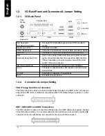
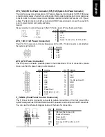
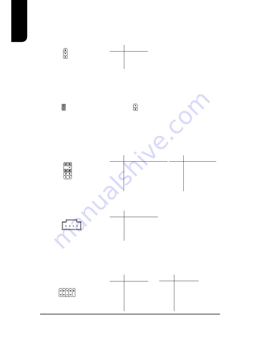
F_AUDIO (Front Audio Connector)

Connects to the audio connector located on the front panel of the system casing (dependent

on case design). When use of the front panel audio connector is required, please remove the

5-6 pin, 9-10pin jumper.  Please note that use of only the front panel audio connector or the

rear panel audio connector is permitted.

CD_IN (Optical Drive Audio Connector)

Connects CD-ROM or DVD-ROM audio connector.

1

PIN

SIGNAL

1

MIC

2

GND

3

MIC_BIAS

4

POWER

5

Front Audio (R)

PIN

SIGNAL

6

Rear Audio (R)

7

Reserved

8

NO PIN

9

Front Audio (L)

10

Rear Audio (L)

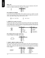
PWR_LED

Connects to the system power LED indicator whereby the power is indicated as ON or OFF.

However, the indicator will flash when the system is suspended.

1

PIN

SIGNAL

1

MPD+

2

MPD-

3

MPD-

PIN

SIGNAL

1

CD_L

2

GND

3

GND

4

CD_R

CLR_CMOS (Clear CMOS)

You can clear the motherboard CMOS with the jumper to return your system to its initial

status. To prevent improper usage, the jumper does not include the jumper plug. If you wish to

use the Clear CMOS function, please short circuit the 1-2Pin.

Open : Normal

Short : Clear CMOS

F_USB1/F_USB2 (Front USB Connector)

Connects to the USB connector located on the front panel of the system casing (dependent on

case design).  Note: Please make sure that each USB connection matches its designated

position.  If connections are made incorrectly, the result can lead to inability to use the function

or even damage.

2

10

1

9

PIN

SIGNAL

6

USB Dy+

7

GND

8

GND

9

NO PIN

10

NC

PIN

SIGNAL

1

POWER

2

POWER

3

USB Dx-

4

USB Dy-

5

USB Dx+

1

10

9

2

1

1

Summary of Contents for XP-M5S661GX

Page 1: ...12MM M5S661GX 1002R User s Manual XP M5S661GX Intel Pentium 4 LGA775 Processor Motherboard...

Page 2: ...is document The content of this document are subject to change without prior notice Gigatrend Technology may make improvements and or changes in the product described in this publication at any time a...

Page 3: ...5 Pentium 4 CPU and Fan Sink 10 2 1 1 Installation of a LGA775 CPU 10 2 1 2 Installation of Fan Sink 11 2 2 Installation of Memory 12 2 3 Installation of the Graphics Card 12 3 BIOSSetup 13 4 DriverIn...

Page 4: ..._MS COMA ATX_12V CD_IN F_AUDIO F_PANEL BATTERY SiS 964 SiS 661GX LGA 775 CPU_FAN ATX FDD IDE2 PCI1 PCI2 PCI3 DDR1 CODEC IT8705AF BIOS VGA IDE1 CLR_CMOS F_USB1 PWR_LED USB LAN DDR2 LPT ICS1883 AGP SYS_...

Page 5: ...IDE1 IDE2 with PIO Bus Master Ultra DMA33 ATA66 ATA100 ATA133 operation modes Can connect up to 4 IDE devices On Board SATA 2 SATA ports support 2 SATA devices with up to 150MB s transfer rate and ca...

Page 6: ...Back Panel PS 2 Keyboard Connects PS 2 standard keyboard and PS 2 standard PS 2 Mouse connector mouse Parallel port LPT Connects to printer COMA Serial port Connects to serial based mouse or data proc...

Page 7: ...p LED NC NC PIN SIGNAL 1 3 3V 2 3 3V 3 GND 4 5V 5 GND 6 5V 7 GND 8 Power Good 9 5VSB stand by 5V 10 12V PIN SIGNAL 11 3 3V 12 12V 13 GND 14 PS_ON soft on off 15 GND 16 GND 17 GND 18 5V 19 5V 20 5V 3 4...

Page 8: ...However the indicator will flash when the system is suspended 1 PIN SIGNAL 1 MPD 2 MPD 3 MPD PIN SIGNAL 1 CD_L 2 GND 3 GND 4 CD_R CLR_CMOS Clear CMOS You can clear the motherboard CMOS with the jumper...

Page 9: ...the placement position 3 Please make sure that an even layer of heat sink paste is added between the CPU and the fan sink 4 Please do not turn on the power prior to installing the fan sink Doing so ca...

Page 10: ...it Align notchs on the two sides of the CPU with the small sockets of the CPU socket and place the CPU straight down 2 Open the load plate and gently remove the plastic cover 1 Push the socket lever...

Page 11: ...sink with the four holes around the CPU socket Push down each fas tener and you should hear a click when the fastener is attached Make sure the four fasteners are attached securely Prior to installat...

Page 12: ...roof insertion design The memory can be installed only when facing the correct position If you cannot insert the module please switch directions 4 It is recommended that memory of similar capacity spe...

Page 13: ...p the CMOS SETUP screen If you wish to enter the BIOS setup please press Ctrl F1 at the BIOS setup screen When using BIOS setup for the first time it is recommended that you save the present BIOS onto...

Page 14: ...to redundancy the drive capacity of the array is the capacity of the smallest drive Due to the fault tolerance if any RAID 1 drive fails data access will not be affected as long as there are other wor...

Page 15: ...double click the Menu exe file Then a MS DOS prompt screen will appear presenting a list of SATA RAID SCSI controllers 3 Select the RAID controller for your motherboard Example select SiS 964 SATA for...

Page 16: ...16 English...

Reviews: