background image

– 6 –

– 7 –

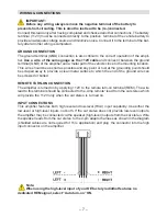
WIRING & CoNNECTIoNS

          IMPoRTANT:


Before any wiring, always remove the negative terminal of the battery to 

prevent short-circuiting. This is also the last lead to be (re-)connected.

Connect this lead only after having completed and checked all other connections. The battery 

terminal (+12V) must be connected directly to the positive  terminal of the vehicle battery to 

provide an adequate voltage source and minimize noise. Connect it to the terminal of the bat-

tery after all other wiring is completed. 

GRoUND CoNNECTIoN


The ground terminal (GND) connection is also critical to the correct operation of the ampli-

fier. 

Use a  wire of the same gauge as the +12V cable

 and connect it between the ground 

terminal (GND) of the amplifier and a metal part of the vehicle close to the mounting location. 

This  wire should be as short as possible and any paint or rust at the grounding point should 

be scraped away to provide a clean metal surface to which the end of the ground wire can 

be screwed or bolted. 

REMoTE TURN-oN CoNNECTIoN


The amplifier is turned on by ap12V to the remote turn-on terminal (REM). The wire 

lead to this terminal should be connected to the „Amp remote“ lead from the car stereo which 

will provide the +12V only when the car stereo is  turned on. 


INPUT CoNNECTIoNS


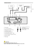
This amplifier features both high level and low-level (RCA) input capability. Use either the 

low-level or high-level inputs, not both. If the car stereo does not provide low-level outputs, 

the amplifier may be connected via the speaker (high-level) outputs from the car stereo. Wire 

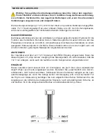
the speaker leads from the car stereo to the 4-pin adaptor harness as shown in the diagram 

(shielded cables are not required for  this  application) and plug  the connector into the high 

input connector on the amplifier.

         Note:


When using the high-level input of your oE factory radiothat features no 

dedicated REM signal, select ”Auto turn-on” oN.

Summary of Contents for AXB20STP

Page 1: ...AXB20STP oWNER S MANUAL BEDIENUNGSANLEITUNG 8 20 CM ACTIVE SUBWOOFER SUBWOOFER SUBWOOFER...

Page 2: ...ease contact your AXTON dealer UNPACKING THE SYSTEM Carefully remove all parts from the giftbox and check whether they are in good undamaged condition and match with the set contents listed below n AX...

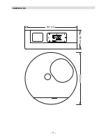
Page 3: ...3 DIMENSIoNS 500 mm 180 mm 500 mm...

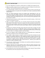
Page 4: ...horized AXTON dealer 7 Be careful not to drain the car battery while using the unit when the car engine is turned off Because the unit uses a considerable amount of energy and the battery will be char...

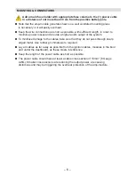
Page 5: ...unit n Lay the signal and power cables separately with enough distance from one another and also from each other wire harness in the car The REM cable to the automatic amp remote output of the radio...

Page 6: ...provide a higher audio output of the system n To minimize damage to the cables take care that they do not pass through sharp edged metal Use rubber grommets were required n Lay all cables as far away...

Page 7: ...ust at the grounding point should be scraped away to provide a clean metal surface to which the end of the ground wire can be screwed or bolted REMoTE TURN oN CoNNECTIoN The amplifier is turned on by...

Page 8: ...ER SETUP 0dB 6dB POWER PRO 50Hz 150Hz LPF GAIN BASS BOOST MIN MAX RCA R L AUDIO INPUTS HIGH LEVEL AXB20STP Active Subwoofer q 20 A R L from Low Level Audio Out of the headunit Use a Y Adapter if you w...

Page 9: ...after input gain has been adjusted it is advisable to fine tune the lowpass crossover frequency for best possible sound quality Note In general setting the lowpass crossover frequency too low will re...

Page 10: ...sich bitte an Ihren AXTON Fachh ndler VERPACKUNGSINHALT Nach dem Auspacken empfehlen wir eine berpr fung von Anzahl und Zustand des Packungsinhalts n AXB20STP Aktiv Subwoofer n High Level Adapter n B...

Page 11: ...11 ABMESSUNGEN 500 mm 180 mm 500 mm...

Page 12: ...tauschen Sollte der Kurzschluss immer noch auftreten wenden Sie sich bitte an Ihren AXTON Fachh ndler 7 Achten Sie darauf dass bei ausgeschaltetem Motor die Batterie des Fahrzeuges nicht entladen wird...

Page 13: ...ein g ngen zu verbinden n Verlegen Sie die Signal und die Stromversorgungskabel m glichst weit voneinander und achten Sie dabei auch auf ausreichenden Abstand von der ab Werk vorhandenen Verkabelung d...

Page 14: ...Sie sowohl die Stromversorgungs als auch die Lautsprecherkabel durch die vorhandenen Kabelkan le n Achten Sie darauf Kabel nicht um scharfe Metall Kanten herum zu verlegen denn sie k nnten leicht bes...

Page 15: ...zu einem geeigneten Karroseriepunkt in der N he Dieses Kabel sollte so kurz wie m glich sein und an einem blanken gereinigten Massepunkt angeschlossen werden AMP REMoTE Der Verst rker wird ber ein 12...

Page 16: ...OFF AUTO TURN ON X OVER SETUP 0dB 6dB POWER PRO 50Hz 150Hz LPF GAIN BASS BOOST MIN MAX RCA R L AUDIO INPUTS HIGH LEVEL AXB20STP Active Subwoofer q 20 A R L des Line Outs vom Steuerger t Benutzen Sie e...

Page 17: ...Bass satt und trocken mit gen gend Tiefbassanteil wiedergegeben wird Diese Einstellung erfolgt genau wie die nachfolgend beschriebenen Eingangsempfindlichkeitseinstellungen rein geh rm ssig EINGANGSEM...

Page 18: ...overed under warranty GARANTIE GEW HRLEISTUNG AXTON gew hrt dem Erstbesitzer auf dieses Produkt bzw seine Einzelteile eine Garantiezeit von 2 Jahren g ltig ab Kaufdatum im Fachhandel Diese vollumf ngl...

Page 19: ...e Please recycle where facilities exist Check with your Local Authority or retailer for recycling advice Waste Electrical and Electronic Equipment Directive Sollten Sie dieses Ger t eines Tages entsor...

Page 20: ......

Reviews: