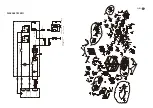
Important:
The inner wheel should be inflated for it has been shipped out with lower pressure (max.
gauge pressure 3bar/0.3MPa)
2. Rubber Feet Assembly (Fig.5)
Hold the rubber feet (12) against the frame as shown in Fig.2. First place the bolt
through the hole in the frame and the hole in the rubber feet and secure it with the nut.
Then secure the other three bolts and nuts with the same procedure.
3. Transport Handle Assembly (Fig.6 & Fig.7)
Place the carry handle (21) through the bracket and fix it with the push bar assembling
set (19). Then place the bolt with a gasket through the hole in the frame and the push
bar assembling set(19). And secure it with a washer and nut as shown in Fig.6 & Fig. 7)
The user can adjust the position of carry handle for removing the machine via release
the push bar assembling set (19) and rotated the carry handle (21) to horizontal position.
4. Environmental protection
- Dispose of soiled maintenance material and operating materials at the appropriate
collection point.
- Recycle packaging material, metal and plastics.
5. Connecting to earth
The housing is allowed to be connected to earth in order to discharge static electricity.
To do this, connect one end of a cable to the earth connection (11) on the generator
and the other end to an external earth (for example an earthing rod).
CAUTION!
Read all safety regulations and instructions.
Any errors made in following the safety regulations and instructions may result in
an electric shock, fire and/or serious injury.
Keep all safety regulations and instructions in a safe place for future use.
ELECTRICAL SAFETY
1. Electrical equipment (including lines and plug connections) should not be defective.
2. The generating set must not be connected to other power sources, such as the power
company supply mains.
3. Protection against electrical shock depends on circuit breaker specially matched to
the generating set. If the circuit breakers require replacement they must be replaced
with a circuit breaker having identical ratings and performance characteristics.
4. Generating sets may only be loaded up to their rated power under the rated ambient
conditions. If generating set use is under conditions which do not conform to the
reference conditions as stipulated in this part of ISO 8528-8:2016, 7.1, if cooling of the
engine or alternator is impaired, e.g. as result of operation in restricted areas, and use
in higher temperatures, altitudes and humidity than those given in the reference
conditions, a reduction in power is necessary.
5. Due to high mechanical stresses only tough rubber-sheathed flexible cable(in
accordance with IEC 60245-4) or the equivalent should be used. When using extension
lines or mobile distribution networks the resistance value shall not exceed 1.5 Ω. For
reference, the total length of lines for a cross section of 1.5 mm² should not exceed
60 m; for a cross section of 2.5 mm², this should not exceed 100 m.
PRE-OPERATION CHECK
1. Wheel assembly (Fig.2 & Fig.3 & Fig.4)
- First place one end of the bolt(16) in the wheel assembly set (16) through the hole in the
frame and secure it with a nut and washer.
- Put the wheel(18) through another end of the bolt in the wheel assembly set (16) and
place the wheel, washer and secure it with the nut.
- Place the wheel cover and secure it via clip as designed on the inner side of the
cover.
- Assemble the left side wheel with same procedure as above.
100
99
|
GB

