background image

Installation and

Operation

The Ayre K-1x is easy to hook up and use. The following
guidelines will ensure that the installation goes smoothly.

Location

The Ayre K-1x comprises two components - the main
preamplifier and the external power supply, which are
joined by an umbilical cable. A detachable connector allows
these units to be temporarily separated for easy installation.

The preamplifier’s power
supply emits a mild hum

field, and should be located

away from other components.

The main unit produces very little heat and can normally be
stacked with other components. However, in certain
situations, hum can be induced into the audio circuitry. In
this case, try separating the components by a few feet (one
meter or so) to isolate the interfering component.

The receiver for the optional infrared remote control is
mounted behind the left-most scallop on the preamplifier’s
front panel. Although the transmitter’s beam will reflect off
of most wall surfaces, a direct line of sight from the
listening position will ensure the maximum range. The
beam will also travel through glass if necessary.

Page 3

Summary of Contents for K-1x

Page 1: ...A y r e K 1x Preamplifier Owner s Manual...

Page 2: ......

Page 3: ...Table of Contents Welcome to Ayre 2 Installation and Operation 3 Optimizing the Phono Stage 9 Numbers and Specifications 13 In Case of Trouble 14 Statement of Warranty 16 A Place for Notes 19...

Page 4: ...iers The warmth and immediacy of a live performance are apparent from the first listening The combination of superb resolution and a natural relaxed quality will draw you into the music time and time...

Page 5: ...ted away from other components The main unit produces very little heat and can normally be stacked with other components However in certain situations hum can be induced into the audio circuitry In th...

Page 6: ...not installed in your system input 6 performs like the other unbalanced inputs If the optional phono stage is installed it will use input 2 Do not connect a high level source to the phono input If th...

Page 7: ...ase note that the unbalanced outputs invert absolute polarity When using an unbalanced connection between the Ayre K 1x and your power amplifier it is suggested that the speaker cables plus and minus...

Page 8: ...t the unit is ready for play though the unit remains muted When the listener toggles the mute control the unit is operational and the indicator light glows blue Should the AC line lose power the pream...

Page 9: ...th balanced inputs unity gain occurs when the volume control is 10 steps below the maximum setting see illustration Since the tape record selector Record is controlled separately from the main input s...

Page 10: ...n with the volume control turned fully up If required the gain of the line stage can be increased 6 dB to compensate for this loss Please contact your authorized Ayre dealer or the factory for informa...

Page 11: ...s are not equipped with XLR connectors there are two choices for making the proper connection 1 Use an RCA to XLR adapter This often may be the easiest solution to implement but introduces an extra se...

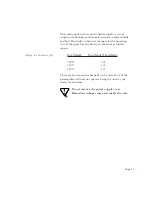
Page 12: ...e Output Phono Gain Gain Resistor Less than 1 0 mV 60 dB 10 1 0 mV to 3 0 mV 50 dB 75 Greater than 3 0 mV 40 dB 249 These are guidelines only Variations from these settings are perfectly acceptable It...

Page 13: ...ols are required 5 64 allen wrench supplied Small screwdriver 0 080 to 0 100 2 0 to 2 5 mm Tweezers or small needle nose pliers Changing the phono gain and loading resistors is comparable in complexit...

Page 14: ...by the two screws in the terminal strip forming a gas tight connection for optimum sound quality To remove the installed resistors use a small flat bladed screwdriver to loosen the two screws in the t...

Page 15: ...e Line 10 k each phase Input Impedance Phono Adjustable 50 k factory setting 100 249 499 1000 loading resistors supplied Other values available upon request Output Impedance 300 each phase Power Consu...

Page 16: ...lue Check all connections on the rear panel to make sure they are secure Symptom Status indicator lamp not lit 1 Be sure that the power supply unit is connected to a working AC outlet 2 Check the AC l...

Page 17: ...he spare fuse also blows do not attempt further repairs Always use the correct fuse Line Voltage Fuse Rating Time Delay 100 V 1 A 120 V 1 A 230 V 1 A There are no user serviceable parts in the Ayre K...

Page 18: ...authorized Ayre dealer or distributor A complete statement of warranty is given below Warranty Statement 1 Ayre Acoustics Inc Ayre warrants the materials and workmanship of this product for a period o...

Page 19: ...therefore reserves the right to make improvements on its products without necessarily assuming an obligation to retrofit such changes upon its previously manufactured models 5 The above warranty is t...

Page 20: ...e unit must not have been altered or removed 7 Warranty registration cards must be completed and mailed to Ayre within 30 days of purchase Ayre may at its option require from the purchaser valid proof...

Page 21: ...A Place for Notes Page 19...

Page 22: ...Revision 1 3...

Page 23: ......

Page 24: ...Ayre Acoustics Incorporated 2300 B Central Avenue Boulder Colorado 80301 303 442 7300 www ayre com...

Reviews: