10
ASSEMBLY INSTRUCTIONS
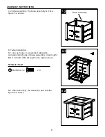
9-1
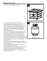
9-2
TT
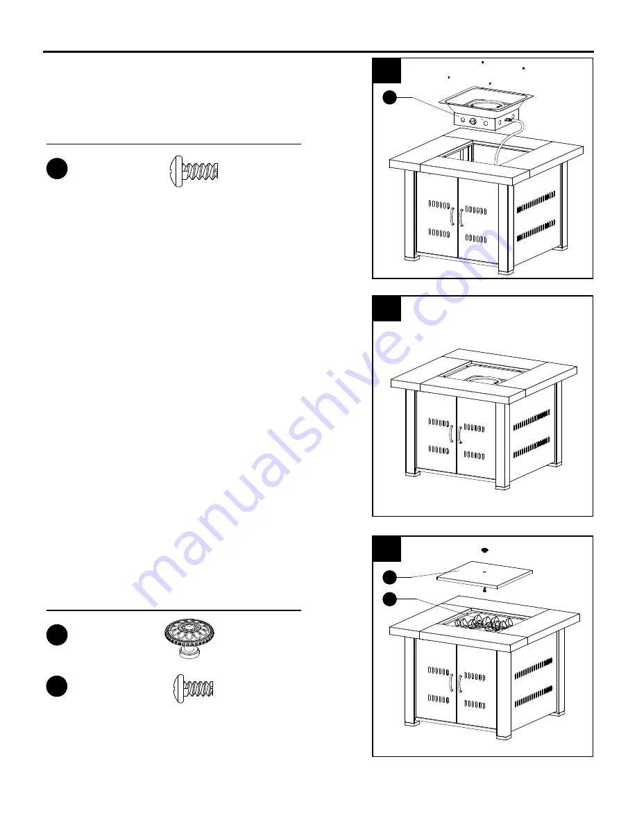
9. Burner Installation
9-1. Line up holes in the burner assembly (B) with
corresponding holes in the table assembly, insert four
M5X8 screws (FF) through holes, fasten them.
9-2.The total assembly parts will like the figure 9-2
shows.
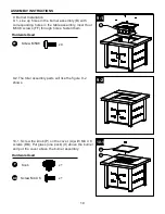
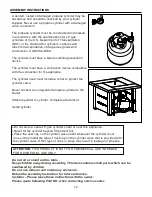
10-1. Screw the knob (P) on the cover (A) with M4 X 8
screws (BB). Put glass (one pack) (II) above the burner
and put the cover above the burner assembly.
10-1
Hardware Used
FF
x 4
Screw M5X8
Hardware Used
P
x 1
Knob
B
II
A
BB
Screw M4 X 8
x 1


