2-8
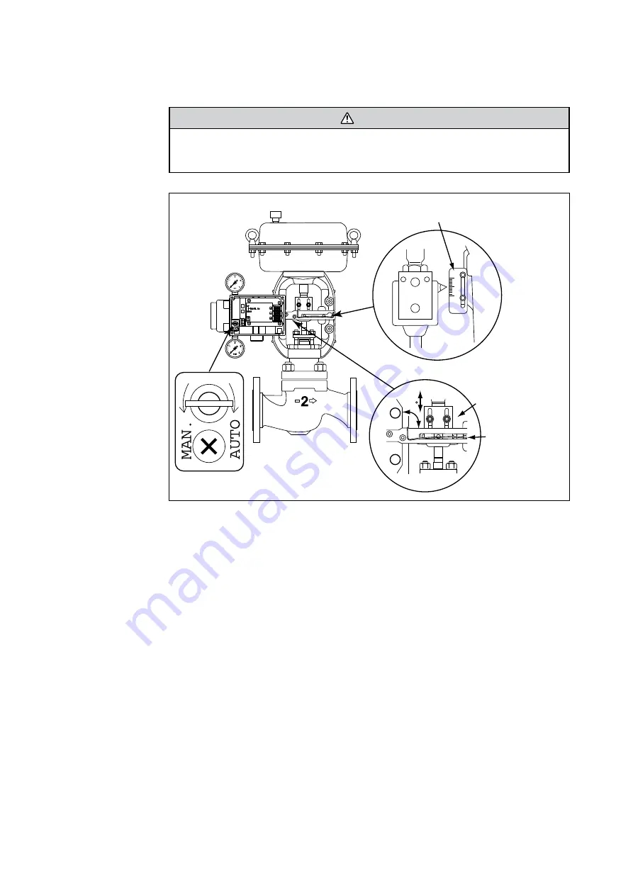
2-4. Initial SVP adjustment
WARNING
Switching the SVP air supply from automatic to manual will divert air directly to the
actuator, actuate the control valve and affect the process. Take the necessary precautions
before turning the A/M switch.
Valvetravel indicator
at 50% travel
Stem connector pin
assembly
Feedback lever
90
Fig. 2-7.
This step in the assembly is to ensure the correct initial relationship between the air supply
and the feedback lever position.
(1) Using a flat-head screwdriver, rotate the A/M switch 180° counter-clockwise. This puts the
SVP in Manual or bypass mode, allowing the regulator valve to change valve position. The
supply and output air pressure gauges should both have the same reading.
(2) Position control valve to mid-travel (50% position) by adjusting air pressure regulator
valve.
(3) Adjust the stem connector pin assembly so that the SVP feedback lever is horizontal and
the stem connector pin forms a 90° angle with the feedback lever.
(4) Set the SVP back to Auto mode using a flat-head screwdriver to rotate the A/M switch
180° clockwise.
Summary of Contents for 100 Series
Page 1: ...CM2 AVP100 2001 Smart Valve Positioner 100 Series Model AVP100 102 User s Manual ...
Page 12: ...1 4 ...
Page 28: ...2 16 ...
Page 36: ...4 4 4 2 1 Menu Tree ...
Page 75: ......
Page 78: ......
Page 80: ......


