background image

AB-6526

17


z

4–20 mA DC input

(Model VY513_)

Precautions


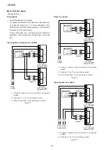
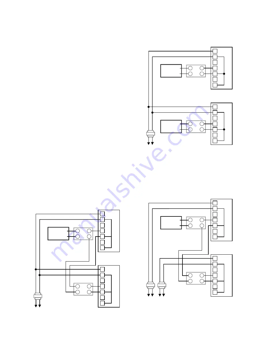
Power transformer is shared   
If a power transformer is shared by two products, 
connect the terminal 

 of each actuator to the 

transformer with the same polarity. Connect the 
terminal 

 in the same way.   


It the terminals are connected with different 
polarities, the product may break down  (see Fig. 
21) .


Control signals are shared for 4–20 mA DC input 
The 4–20 mA DC input signals of this product are 
not isolated from the power.    


And, the input impedance of 4–20 mA DC 
signals is 100 Ω. The relations among the input 
impedance of the product, the output load 
resistance of the controller, and the output load 
resistance and input impedance of an isolator 

(if necessary)  must meet the following formula. 

Applicable load resistance > Total of input 
impedance 


If two products are operated by one controller, 
configure the system referring to Fig. 22 for two 
individual transformers, Fig. 20 for a shared 
transformer. To share a power transformer, install 
an isolator to the 4–20 mA DC input terminals of 
the second product. Otherwise, the product will 
malfunction.

Input signals and power are shared

Model R35TC0,

Model R36TC0

ACTIVAL

4-20 mA DC input

 (Model VY513

_

)

Isolator


2

3

3

1

1


2
3
4
5
6
7

ACTIVAL

4-20 mA DC input

 (Model VY513

_

)

Isolator

(mandatory)

Power

suppply

2

1


2
3
4
5
6
7

*

1  Provide an isolator for the controller that is not internally 

isolated.

*

2  Terminals 2, 5, and 7 are internally connected.

*

3  Refer to notes under “Power transformer is shared.”

Figuar 20 

Power is shared

Model R35TC0,

Model R36TC0

ACTIVAL

4-20 mA DC input

 (Model VY513

_

)

Isolator


2

1

1

1


2
3
4
5
6
7

Model R35TC0,

Model R36TC0

ACTIVAL

4-20 mA DC input

 (Model VY513

_

)

Isolator

Power

supply


2

1


2
3
4
5
6
7

*

1  Provide an isolator for the controller that is not internally 

isolated.

*

2  Terminals 2, 5, and 7 are internally connected.

Figuar 21 

Input signals are shared

Model R35TC0,

Model R36TC0

ACTIVAL

4-20 mA DC input

 (Model VY513

_

)

Isolator


2

1

1

3

1


2
3
4
5
6
7

ACTIVAL

4-20 mA DC input

 (Model VY513

_

)

Isolator

Power

supply

Power

supply

2

1


2
3
4
5
6
7

*

1  Provide an isolator for the controller not internally isolated.

*

2  Terminals 2, 5, and 7 are internally connected.

*

3  Provide an isolator if no isolator is provided to the 4–20 

mA DC input of the first actuator AND the applicable load 

resistance of controller is less than 200 Ω.

Figuar 22 

Summary of Contents for ACTIVAL VY51 5H006

Page 1: ...900_Z insertion type Thermostat Model TY9800 4 20 mA DC input Provides proportional control in combination with a DDC controller e g Infilex GC Model WY5111 Model R35 R36 2 10 V DC input Provides proportional control in combination with a DDC controller e g Infilex AC Model WY5117 Features Compact and lightweight Valve and actuator integrated in a single unit Conforms to IP54 dust proof splash pro...

Page 2: ...nded design life of this product is 10 years The recommended design life assumes that maintenance such as replacement of the limited life parts is carried out properly Refer to the section on maintenance in this manual Warnings and Cautions WARNING Alerts users that improper handling may cause death or serious injury CAUTION Alerts users that improper handling may cause minor injury or material lo...

Page 3: ...sition and securely fasten it to the pipes Excessive tightening or improper installation position may damage the valve After installation make sure no fluid leaks from the valve pipe connections Improper piping may cause fluid leakage outside of the valve Do not put a load or weight on this product Doing so may damage the product Installation and wiring of the actuator must be performed by personn...

Page 4: ...l resistance Nominal 1 kΩ Operation range 0 fully closed to 100 fully open Max applied voltage 5 V DC Note It cannot be connected with Model M904E Valve flange adapter kit 4 Valve Valve size Major materials 83168456 001 DN15 002 DN25 Hot rolled steel SS400 Galvanized 003 DN40 004 DN50 005 DN65 006 DN80 101 DN15 Non galvanized 102 DN25 103 DN40 104 DN50 105 DN65 106 DN80 Outdoor cover DY3001A1017 M...

Page 5: ...llation location Indoor use Note Salt air corrosive gas flammable gas and organic solvent must be avoided Outdoor use Note Salt air corrosive gas flammable gas and organic solvent must be avoided And use the outdoor cover to be ordered separately etc to avoid direct sunlight Mounting position Refer to Installation Mounting position Manual operation Prohibited Insulation resistance Between terminal...

Page 6: ...ange FF body cast iron FC200 Raised face flange RF body stainless steel SCS13A Applicable fluid Chilled hot water high temperature water steam brine glycol concentration 50 or less Temperature of fluid 0 175 C Flow characteristics Equal percentage characteristic Rangeability 100 1 Leakage from valve seat 0 01 of the rated Cv max 0 0006 of Cv for DN15 Major materials Body Cast iron FC200 Stainless ...

Page 7: ...gnal for valve position applied for the 4 20 mA DC input and 2 10 V DC Input Output voltage range 2 V DC fully closed to 10 V DC fully open Maximum load resistance 10 kΩ or more max output current 1 mA Valve position indication Indicator 0 fully closed to 100 fully open Can be seen from the forward backward or lower position Wiring Screwed on the terminal block M3 5 tightening torque 0 8 1 0 N m N...

Page 8: ...r Valve size L L1 H H1 φ D φ C t φ h N VY51_5K001_ DN15 108 50 265 75 95 70 16 15 4 VY51_5K002_ DN25 127 60 280 90 125 90 18 19 4 VY51_5K004_ DN40 165 82 5 293 103 140 105 20 19 4 VY51_5K005_ DN50 178 89 297 107 155 120 20 19 4 VY51_5K006_ DN65 190 90 314 124 175 140 22 19 4 VY51_5K008_ DN80 203 100 315 125 185 150 22 19 8 Table 2 Dimension table for Model VY51_5H00_ _ JIS 10K FC200 high different...

Page 9: ... φ D φ C Dia g t φ h N VY51_6K001_ DN15 108 50 265 75 95 70 51 12 15 4 VY51_6K002_ DN25 127 60 280 90 125 90 67 14 19 4 VY51_6K004_ DN40 165 82 5 293 103 140 105 81 16 19 4 VY51_6K005_ DN50 178 89 297 107 155 120 96 16 19 4 VY51_6K006_ DN65 190 90 314 124 175 140 116 18 19 4 VY51_6K008_ DN80 203 100 315 125 185 150 126 18 19 8 Table 4 Dimension table for Model VY51_6H00_ _ JIS 10K SCS13A high diff...

Page 10: ...AB 6526 10 Parts Identification Actuator Yoke Valve body Pointer Pointer Terminal cover Top cover Knockout hole Top cover Spring unit Lid Stem Gland packing Seat ring plug Figuar 3 Parts identification ...

Page 11: ... steam 80 or more mesh If the strainer cannot be installed just before the inlet of each valve install it on the pipe diverting sections for each piping group Do not install this product near a steam coil hot water coil etc High temperature radiant heat may cause failure of the actuator Avoid connecting the product to piping where water hammer may occur or slag etc easily collects Install the prod...

Page 12: ...the valve seat and the valve may not be fully closed 3 Fully open the valve and flush the pipes at the maximum flow rate When fluid flows for the first time it is to clean out the foreign matter and refuse in the pipes The valve is set to fully closed when it is shipped from the factory CAUTION After installation make sure no fluid leaks from the valve pipe connections Improper piping may cause fl...

Page 13: ... burnout z z How to maintain IP54 dust proof splash proof In order to maintain IP54 performance use a waterproof connector or a water resistant plica tube when the product is used in high humidity environment or outdoor Be sure to completely close the terminal cover and top cover Apply a waterproofing treatment for the knockout hole For cable connection use the waterproof connector to be ordered s...

Page 14: ...ed controller circuit E Voltage supplied by the controller V Voltage between 4 and 6 Figuar 9 z z Nominal 135 Ω resistance input Model VY512_K00_ _ Model VY512_H00_ _ 4 5 6 7 To controller 24 V AC power Open Open R B W T2 T1 1 3 2 Figuar 10 z z 4 20 mA DC input Model VY513_K00_ _ Model VY513_H00_ _ 4 5 6 4 20 mA DC inputs to controller 2 10 V DC feedback signals 24 V AC power Open T2 T1 1 3 2 7 No...

Page 15: ...l R35 Model R36 ACTIVAL 4 20 mA DC input Model VY513_ 4 5 6 7 T1 T2 2 1 1 3 2 Power transformer Model AT72 J1 100 200 V AC 1 The terminal 2 power terminal 5 4 20 mA DC input and terminal 7 2 10 V DC feedback signal are internally connected 2 Input impedance of 4 20 mA DC input of the actua tor is 100 Ω 4 20 mA DC input is not isolated Install the power trans former separately Figuar 15 Connection ...

Page 16: ...vice life the minimum opening position cannot be maintained Avoid instrumentation that may cause secondary dam age in case of abnormality Figuar 17 Using relay interlock ACTIVAL Nominal 135 Ω resistance input Model VY512_ 4 5 6 7 OPEN XO XC 1 3 2 T1 T2 W B R Proportional controller Model TY900_Z OPEN 100 CLOSE 0 W B R XO XC Power transformer Mode AT72 J1 100 200 V AC Fully open when interlocked Fu...

Page 17: ...e product will malfunction Input signals and power are shared Model R35TC0 Model R36TC0 ACTIVAL 4 20 mA DC input Model VY513_ Isolator 2 3 3 1 1 2 3 4 5 6 7 ACTIVAL 4 20 mA DC input Model VY513_ Isolator mandatory Power suppply 2 1 2 3 4 5 6 7 1 Provide an isolator for the controller that is not internally isolated 2 Terminals 2 5 and 7 are internally connected 3 Refer to notes under Power transfo...

Page 18: ...ted 2 Terminals 2 5 and 7 are internally connected 3 Refer to notes under Power transformer is shared Figuar 23 Power is shared Model WY5117 Model WY5117 ACTIVAL 2 10 V DC input Model VY514_ Isolator 2 3 1 3 1 1 com com 2 3 4 5 6 7 ACTIVAL 2 10 V DC input Model VY514_ Isolator Power supply 2 1 2 3 4 5 6 7 1 Provide an isolator for the controller that is not internally isolated 2 Terminals 2 5 and ...

Page 19: ...long period execute valve open and close operations once a month or so Execute maintenance according to table 5 Once every six months or so visually check that there is no leakage of fluid to the outside of the valve and the actuator operates smoothly if a trouble occurs as described in Table 6 take appropriate measures according to the symptom Although the measures are taken if the trouble cannot...

Page 20: ...e and differential pressure at the secondary Stability of control Adjust the mounting conditions Adjust the settings of control parameter such as PI It takes shorter time to return the valve from fully open to fully closed Check wiring for the braking motor Contact Azbil Corporation It takes longer time to return the valve from fully open to fully closed Valve does not return Check the operation to...

Reviews: