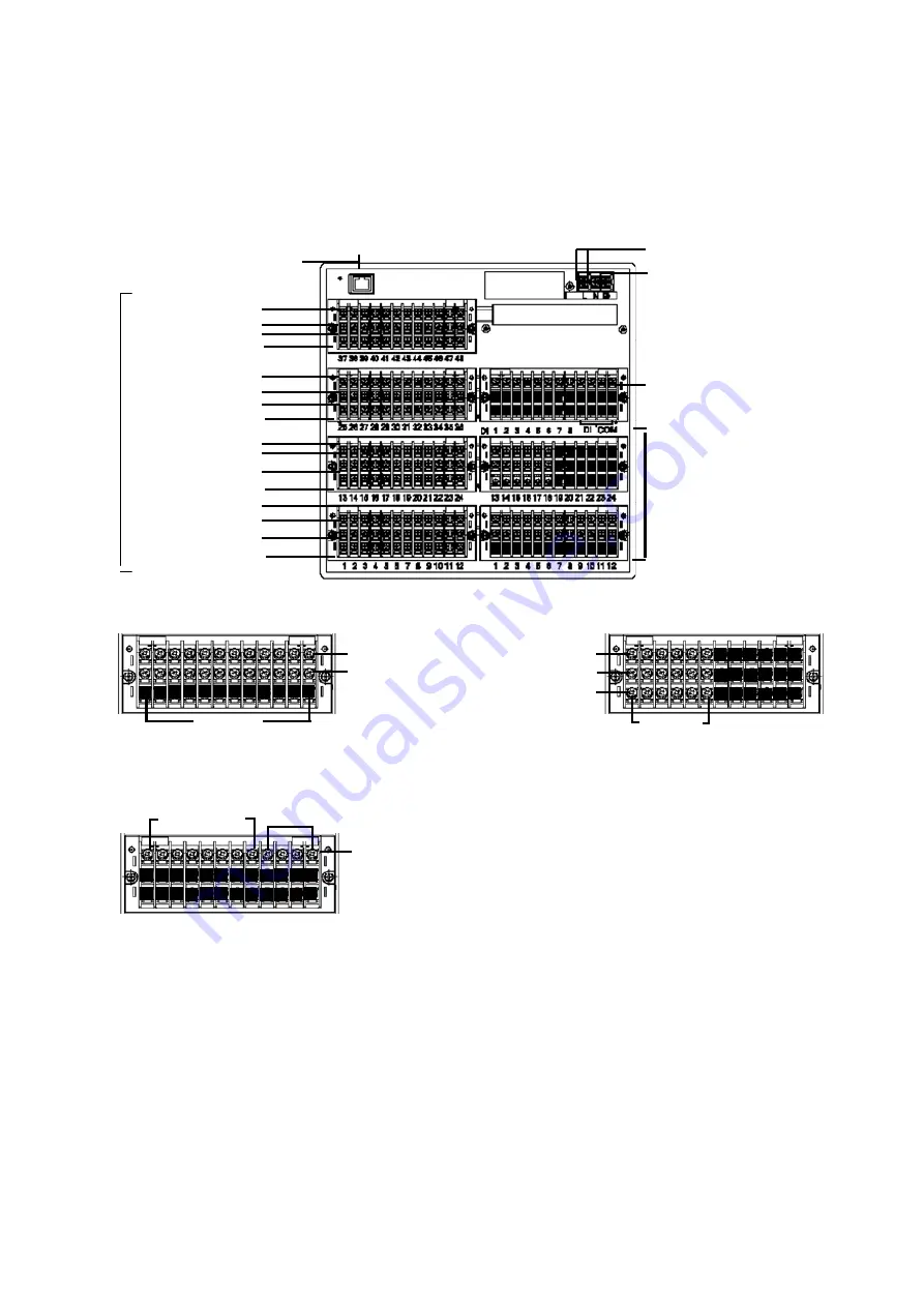
3.4. Terminal Block
The following figure shows the terminal block as configured for options (alarm relay outputs [12
Form A contacts, 6 Form C contacts] and 8 contact inputs). The Ethernet connector is the standard
type.
[Option terminal blocks (* Subject to change)]
N.O. terminals
COM terminals
Terminal
Nos.1-12
Non-voltage contacts inputs
Terminal Nos.1-8
COM terminals
N.C. terminals
COM terminals
N.O. terminals
Terminal
Nos.1-6
• 8 non-voltage contact inputs
• Alarm relay outputs (6 normally closed contacts)
• Alarm relay outputs (12 normally open contacts)
[CH1-12]
Power terminals
Ethernet connector
Protective ground terminals
TC, mV(+), RTD (A) terminals
TC, mV(-), RTD (B) terminals
RTD
(B)
terminals
[CH13-24]
[CH25-36]
[CH37-48]
M
eas
ur
em
e
nt
in
pu
t
ter
m
ina
l b
loc
ks
Alarm relay outputs (2 options)
• 12 N.O. contact terminal block
• 6 N.C. contact terminal block
* ARF2 _ _ _ _ 5 _ _ _ _,
ARF2 _ _ _ _ F _ _ _ _
• Upper: Terminal block for N.O. output
• Lower: Terminal block for N.C. output
Non-voltage contact inputs (option)
• 8 non-voltage contact inputs (common)
TC, mV(+), RTD (A) terminals
TC, mV(-), RTD (B) terminals
RTD (B) terminals
TC, mV(+), RTD (A) terminals
TC, mV(-), RTD (B) terminals
RTD (B) terminals
TC, mV(+), RTD (A) terminals
TC, mV(-), RTD (B) terminals
RTD
(B)
terminals
8


