49
Chapter 6. Maintenance and Inspection
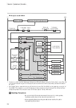
Failure inspection flowchart
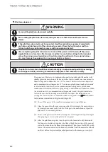
WARNING
Before mounting, removing, or wiring, be sure to turn off the power to this device and all
connected devices. Failure to do so may result in electric shock.
If there is a problem with the equipment, follow the inspection procedure below.
N
Turn the start input OFF
and reset by pressing
the RESET switch
Change the voltage to
within the allowable range
Disconnect the flame
detector wiring
Does pilot
burner ignite?
*
Is power within
the allowable voltage
range?
Is the flame LED
of this device OFF?
Did the flame LED
turn OFF?
Replace this device
Replace this device
Replace this device
Does main burner ignite?
Extinguished?
Alarm sounds?
Was the flame LED
of this device lit?
• Inspect wiring of this device
• Replace this device
• Inspect burner
• Inspect flame detector
• Inspect panel power
switch and fuse
• Inspect wiring
• Inspect burner (false flame)
• Inspect flame detector
• Inspect main valve
• Inspect burner and wiring
• Check for leak from main valve
• Inspect burner
Check airflow switch air and
check for disconnection
• Inspect alarm function
• Inspect this device
Close manual valve
for main burner
Normal
Is there voltage betw.
terminals 4 & 5, and
betw. 6 & 7?
Is flame voltage 2 V
or more?
Is there voltage betw.
terminals 4, 5, and 8?
Is power supplied
to terminals 2 & 3?
Turn ON the start input
Is start
input of this device
connected correctly?
Does 7-segment display
say “
P 1
”?
Does error occur
soon after startup?
• Inspect start input terminals
(21, 19, and 20) of this device
• Inspect the start input
Is flame simulator
flame LED lit?
Inspect airflow and
lockout interlocks
• Inspect pilot, ignition t
ransformer, and wiring
• Do ignition spark response test
• Inspect burner
*
N
N
N
N
N
Y
Y
Y
Y
Y
N
N
N
N
N
N
N
Y
Error occurs
during prepurge?
Y
N
Y
Y
Y
Y
Y
Y
Y
N
Y
Y


