A-22
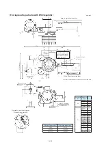
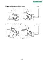
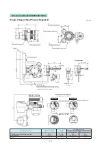
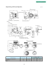
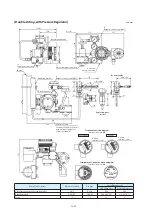
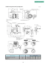
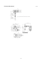
[Double-Acting, with Pressure Regulator]
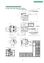
unit: mm
150
(270)
179
161
*2
Supply air connection
2B pipe
Auto/manual switch
Mounting bracket
U bolts and nuts
*3
41
41
±4° to ±20°
137
92 to 122
*4
298
Dedicated cable
Fasten properly in accordance
with electrical equipment
technical standards.
21
70
98
*2
Output air connection (OUT1)
*1 Electrical
wiring connection
Air set
*1
Electrical wiring connection
72
46
83
72
22
Explosion-proof
model
237
Ground
terminal screw
Ground
terminal screw
Terminal box terminal connection diagram
Terminal screw size: M4
Terminal connection diagram
Terminal screw size: M4
AVP200/202
AVP201
For rotary valve
*2
Output air connection (OUT2)
138
97
Main Unit Structure
Electrical conduit
Air pipe
Installation Screws
AVP Main Unit
Position Detector
TIIS flameproof model, regular model
G1/2
Rc1/4
M8
M6
Regular model
1/2NPT
1/4NPT
5/16-18UNC
1/4-20UNC
Notes
*1
*2
*3
*4
Summary of Contents for AVP200
Page 30: ......
Page 66: ...2 28...
Page 80: ...4 4 Menu Tree...
Page 120: ...5 16...
Page 128: ...6 8 For models those date of manufacture are before September 2017...
Page 130: ...6 10 For models those date of manufacture are before September 2017...
Page 132: ...6 12 For models those date of manufacture are before September 2017...
Page 136: ...6 16 For models those date of manufacture are after October 2017...
Page 138: ...6 18 For models those date of manufacture are after October 2017...
Page 184: ...Appendix A Specifications A 25...
Page 185: ......
Page 188: ......
Page 190: ......

