2-20
2.3.2 Attachment to the actuator of the valve travel detector
■
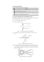
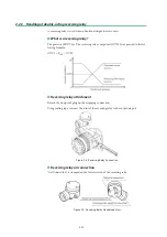
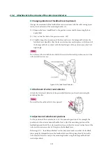
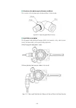
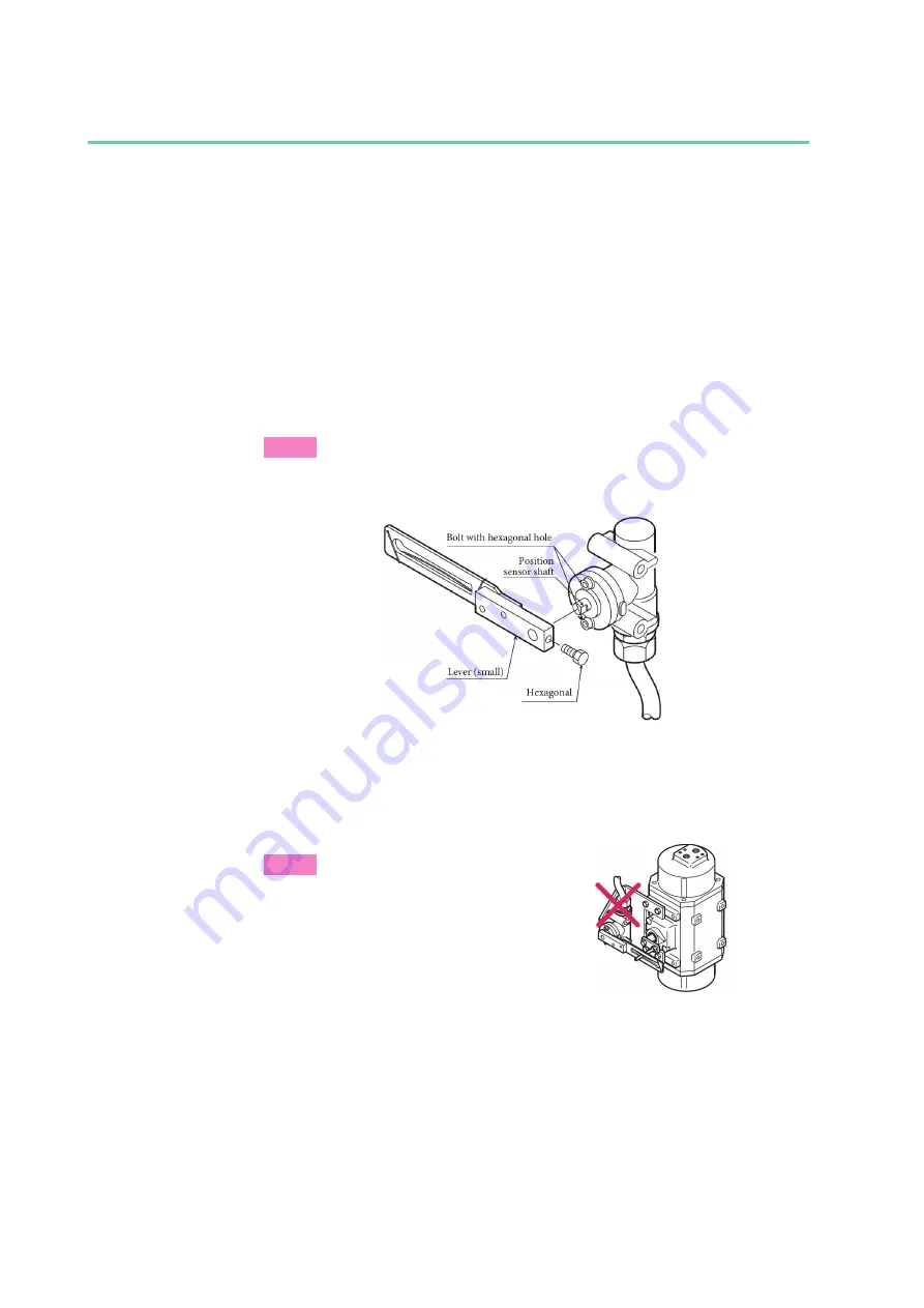
Changing direction of feedback lever (optional)
Change the orientation of the feedback lever in accordance with the cable wiring orien-
tation, the constraints of the mounting bracket, etc.
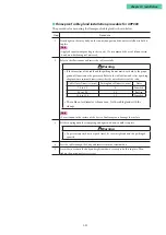
(1) Remove the lever (small) fixed to the position sensor shaft by removing the hex-
agonal bolt.
(2) Next, rotate the shaft of the position sensor 180°.
(3) Finally, change the orientation of the lever and screw the hexagonal bolt into the
feedback lever (small) so that the lever is fastened securely in place, with the end of
the hexagonal bolt in contact with the beveled part of the position sensor shaft at a
right angle.
Note
Do not loosen the two bolts hex socket bolt screws that fasten the position sensor to the
valve travel detector case.
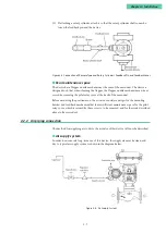
Figure 2-20. Valve Travel Detector
■
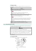
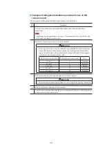
Attachment of valve travel detector
Attach the valve travel detector to the prescribed locations on the actuator using the
mounting bracket.
Note
Do not allow the cable outlet to face upward.
■
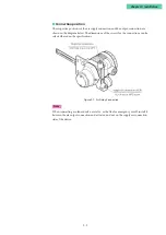
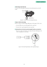
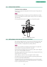
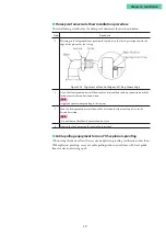
Adjustment of attachment positions
Set the position of the control valve to 50 % by manual operation of, for example, the
positioner or the actuator manual handle. Next, adjust the mounting position of the
feedback pin and that of the valve travel detector such that the central vertical axis of the
valve travel detector reaches a 90° angle to the feedback lever.
Referring to 2.2, “Installation Method,” in this document, make sure that the feedback
pin is properly clamped between the feedback lever and the spring. Finally, fasten the
valve travel detector securely to the mounting bracket using the hexagonal bolts and
washers provided.
Summary of Contents for AVP200
Page 30: ......
Page 66: ...2 28...
Page 80: ...4 4 Menu Tree...
Page 120: ...5 16...
Page 128: ...6 8 For models those date of manufacture are before September 2017...
Page 130: ...6 10 For models those date of manufacture are before September 2017...
Page 132: ...6 12 For models those date of manufacture are before September 2017...
Page 136: ...6 16 For models those date of manufacture are after October 2017...
Page 138: ...6 18 For models those date of manufacture are after October 2017...
Page 184: ...Appendix A Specifications A 25...
Page 185: ......
Page 188: ......
Page 190: ......

