(09)
1-12-2 Kawana, Fujisawa
Kanagawa 251-8522 Japan
URL
: http://www.azbil.com
Specifications are subject to change without notice.
2
■
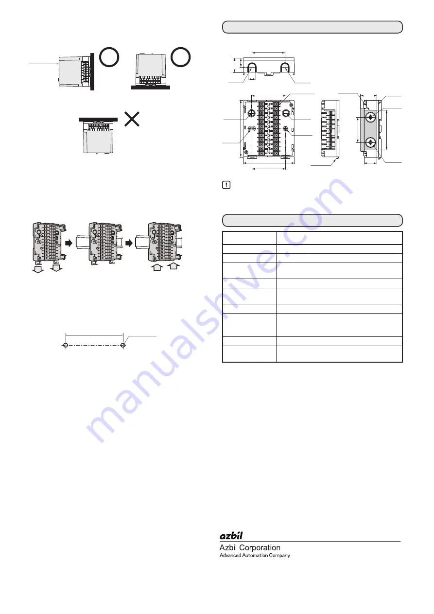
Installation Orientation
Attach the unit in the orientation shown below.
Do not install it in the orientations illustrated below.
■
Mounting on DIN Rail
(1) Pull down the sub-base's DIN rail clamps.
(2) Attach to the DIN rail while checking above and below the
sub-base.
(3) Push up the DIN rail clamps to attach the sub-base (sold
separately) to the DIN rail.
■
Mounting in a Panel
(1) Drill two M4 screw holes into the panel.
(Units: mm)
(2) Use screws to mount the sub-base on the panel.
(Maximum tightening torque: 1.2N · m)
(Units: mm)
Handling Precautions
•
Be sure to t
ighten the terminal screw (maximum tightening torque:
0.5N · m)
Item
Description
Model Number
BC-R05A100
Weight
Approximately 200 g
Ambient
temperature
-20 to +60 °C
Sold separately
Sideboard Model No.: 81447515-001
Material
Denatured PPE resin (black) UL94-V0 PTI250
Material group III a
Wiring types
Refer to each BC-R instruction manual
Vibration (transport) 0 to 9.8 m/s
2
(10 to 150 Hz 1 octave/min 10 cycle xyz each
direction)
Shock (transport)
0 to 300 m/s
2
Package drop
60 cm drop height (free drop onto 1 corner, 3
edges, 6 sides)
Display area
BC-R
main unit
BC-R
main unit
BC-R
main unit
Pull down the DIN rail
clamps
Push the DIN rail clamps
upward to fix in place
Attach sub-base to DIN rail
62.5
M4
(2 locations)
EXTERNAL DIMENSION
95
62.5
105
27
17
61
64
DIN rail clamp
φ12
Knockout
hole
φ12
Knockout
hole
Sub-base
mounting
hole
Sub-base
mounting
hole
Knockout
hole
Knockout
hole
16
Sub-base
46.6
73.5
Sideboards
M3.5
(terminal screw)
30.7
23.9
φ19
Knockout
hole
φ19
Knockout
hole
SPECIFICATION
1st edition: Feb. 2014 ( K )


