8-4
■
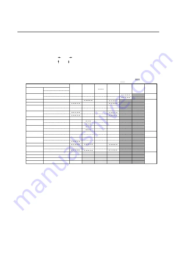
Programming map
As shown below, a programming map consists of columns of segment numbers
and rows of program setting items.
In the program setting state, the items in the solid lines indicated by the segment
numbers and program setting items are displayed.
key
,
key
: moves segments right and left
key
,
key
: moves segments up and down
The figure shows a programming map from the first to the 10th segment.
Programming map example:
*1
: Items up to segment 10 has been entered.
*2
: The event types of each event are listed below.
Event 1/2
: PV upper limit (event type setting 2)
Event 3/4
: time event (event type setting 1)
Event 5
: code event using two points
(event type setting 18, auxiliary setting 2)
Event 7
: time code event using two points
(event type setting 23, auxiliary setting 2)
Event 9 to 16: event off (event type setting 0)
*3
: Use of controller function (setup data
C21
is set to something other than 0)
*4
: These are settings used in each program and are shared by all segments.
Program item
Pattern
Event 1
Event 2
Event 3
Event 4
Event 5
Event 7-1
Event 7-2
PIG group, output
limiter group
G.SOAK
PV shift
Repeat
PV start
Cycle
Pattern link
Tag
Segment number
(1) No.1 setting
(2) No.2 setting
(1) SP
(2) Time
(1) Operating point
(1) Operating point
(1) On Time
(2) Off Time
(1) On Time
(2) Off Time
(1) Code
(1) Code
(2) Time
(1) Code
(2) Time
(1) PID group
(2) Output limiter group
(1) Type
(2) G.SOAK width
(1) Shift value
(1) Return destination segment
(2) Count
(1) Type
(1) Count
(1) Link destination program
(1) 8 character tag
1
100
0:30
1100
0:00
0:01
1
1
0:10
0
0:20
3
3
0
0
0
0
0
PROG9999
2
100
3:00
30
0:00
0:01
0:00
1:00
2
A
1
2
5
0
0
0
0
PROG9999
10
100
10:00
0:00
0:01
3
2
5:00
3
9:00
1
7
1
10
0
0
0
0
PROG9999
11
12 to 99
Remarks
*1
*2
*3
*4
Items cannot be moved to the gray area.
Settings in the gray area are shared with segment 1.
Chapter 8. PROGRAM SETUP


