5-31
■
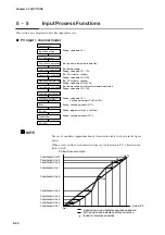
PV input 2 channel model
Analog input 1
Cold junction compensation
Wiring resistance compensation
A/D conversion
Input range type
Square-root extraction
Equalizer (approximation
by linearization table)
Equalizer (approximation
by linearization table)
Upper and lower limit alarm
Temperature unit range
Upper and lower limit value scaling
Ratio
Digital filter
PV shift
Bias
Setting : setup data
C01
(For resistance temperature detector)
(For thermocouple)
Setting: setup data
C07, C10
(For DC current and voltage)
Setting: setup data
C08, C09
(For DC current and voltage)
Setting: setup data
C04 to C06
(For thermocouple and resistance temperature detector)
Setting: setup data
C02, C03
Setting: setup data
C30
Variable parameters
PA51 to PA70
Setting: variable parameter
PA13
Setting: program setting PV shift item
Setting: variable parameter
PA12
PV (PV1)
Setting: variable parameter
PA111
Analog input 2
Cold junction compensation
Wiring resistance compensation
A/D conversion
Input range type
Square-root extraction
Upper and lower limit alarm
Temperature unit range
Upper and lower limit value scaling
Ratio
Digital filter
PV shift
Bias
Setting: setup data
C11
(For resistance temperature detector)
(For thermocouple)
Setting: setup data
C17, C20
(For DC current and voltage)
Setting: setup data
C18, C19
(For DC current and voltage)
Setting: setup data
C14 to C16
(For thermocouple and resistance temperature detector)
Setting: setup data
C12, C13
Setting: setup data
C30
Variable parameters
PA71 to PA110
Setting: variable parameter
PA23
Setting: program setting PV shift item
Setting: variable parameter
PA22
PV2
Setting: variable parameter
PA112
Channel switching
PV
Setting: setup data
C25
to
C29
Chapter 5. FUNCTIONS


