background image

AB-6529 

10 

Wires Connection 

Connection to the power supply terminal block 

Crimp the terminal lugs for the M3 screw terminal block to the 
wire ends, and connect them to the terminal block. 


Connection to I/O modules and NC-bus terminal block 

Since quick-fit screwless terminal block is used for the I/O 
modules and the NC-bus terminal block, the procedure for 
wiring is specified as follows. 

1)  Strip the wire sheath 8 mm. (The gauge for the strip 

length is located at the front lower part of Infilex GD basic 
unit.  If the stripped part is longer than 8 mm, the 
conductor will be exposed, causing electrical shock or 
short circuit between adjacent terminals.  If it is shorter, 
the conductor may not contact the connector.) 

2)  Make sure that no wire fiber is protruded from the 

conductor (stripped wire). 

3)  Press the button on the terminal block deeply enough to 

insert the wire using a slotted screwdriver. 
(Maximum button-pressing force is 14 N.) 

4)  Release the button, and gently pull out the wire 

horizontally to make sure that it is tightly fastened. (If you 
pull out the wire diagonally, it may be disconnected.) 
Make sure that no wire fiber is protruded from the 
conductor (stripped conductor). 


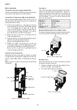
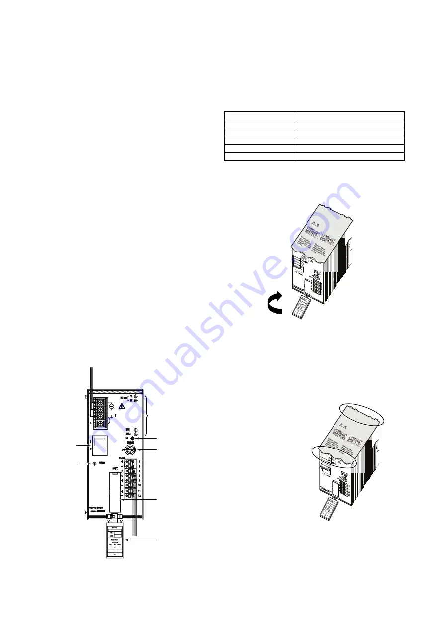
Positions for connected cables 

Neatly place the wires, using cable ties or the like,  connected 
to Infilex GD so as not to hide LED, Data Setter connector, 


mark, S1 switch, battery holder, or indication tag, as shown in 
Fig. 8.   
Make sure there is no slack in the wires from the cable ducts 
to Infilex GD. 


Figure 8.  Connected cables in position 

Tube marker 

Since Infilex GD adopts a quick-fit screwless terminal block, 
wires are connected without crimp terminals.  Therefore, if 
normal tube markers are used, they may come off when the 
wires are disconnected.  To prevent this, use the following 
Flat Tube Marker.  It is held on a wire by friction and thus 
does not come off easily. 

Manufacturer 

Phoenix Contact  

Part name 

Flat Tube Marker 

Part number 

5880029 

Model TMC-3 
Applicable wire size 

0.4 mm

2

 to 2 mm

2


Package unit: 

200 m/roll 


System indication label for the controller number 

The indication tag has the system indication label on its back. 
Turn it over and fill in the controller number on the label. 


Figure 9.  System indication label 


Protective sheet 

After connecting the wires, be sure to peel off the protective 
sheet before turning on the power. 

1)  Adhesive is applied to the sheet approximately 20 mm 

from the front edge.  Peel off this area. 

2)  Tear off the sheet along the perforations. 


Figure 10.  Protective sheet 


Turn over.

Indication tag 

2) Tear off. 

1) Peel off the adhesive area.

LED 

S1 switch 

 
Connector for 
Data Setter 


Battery holder


Indication tag 

Power switch 


LED 

Summary of Contents for Inflex GD WY5110

Page 1: ...d Azbil Corporation s field devices Intelligent Component Series devices are also connectable to Infilex GD via SAnet allowing high performance control Features Compact design Small size body allows free installation in a desired place I O module configurations Input and output types can be selected and the number of points to be mounted can be increased or decreased corresponding to the applicati...

Page 2: ...ce with all applicable safety standards Installation must be carried out according to the operating conditions power temperature humidity vibration shock installation position atmospheric condition etc specified in this manual to prevent equipment damages All wiring must comply with local codes of indoor wiring and electric installation rules Use crimp terminal lugs with insulation for electric wi...

Page 3: ...module to be combined with Infilex GD Model WY5110 separate order is required Regarding I O modules UT module integral type Operator Panel and SAnet interface module to be combined with Model WY5111 refer to AB 6527 Specifications Instructions of Model RY50XX Parts for Installation Part number Description 83165861 001 Screw tab 83104567 001 DIN rail mounting bracket Note For mounting Infilex GD ei...

Page 4: ...ed LED OFF Normal operation Red LED ON Minor failure or system restart Operation Minor failure ERR2 Red LED OFF Normal operation LED indication Communication NC bus Transmit TX Receive RX RAM RTC Lithium battery backup Power failure backup Data file Non volatile memory backup Transmission system Current transmission Transmission speed 4800 bps Transmission distance 500 m Communications NC bus Remo...

Page 5: ...ype Operator Panel UT module and SAnet I F module For the specifications of I O modules UT module and SAnet interface module refer to Specifications Instructions of Model RY50XX AB 6527 For the specifications of integral type of Operator Panel refer to Specifications Instructions of Model RY5001Q QY5100W AB 6546 CE Marking Conformity This product must be installed in a panel cabinet Besides the pr...

Page 6: ...AB 6529 6 Dimensions Figure 3 Dimensions mm 60 90 140 ...

Page 7: ...lex GD basic unit At this time hold the male connector with the mark facing left and insert it as the mark points to the mark on the Infilex GD basic unit 2 Connection of Data Setter Model QY7211B PC MMI Convert the D SUB connector to the mini DIN connector with the conversion cable Part No 83104995 001 At this time hold the male connector with the mark facing left and insert it as the mark points...

Page 8: ...ule UT module integral type Operator Panel and or SAnet I F module to be assembled Their dimensions are the same Width of Infilex GD One module 30 mm n quantity Infilex GD basic unit 60 mm Notes Panel mount type Operator Panel is not directly assembled with Infilex GD To connect it to Infilex GD a UT module is required For details of panel mount type Operator Panel please refer to Specifications I...

Page 9: ...UT module integral type Operator Panel and or SAnet I F module to be assembled Their outside dimensions are the same Width of Infilex GD One module 30 mm n quantity Infilex GD basic unit 60 mm Notes Panel mount type Operator Panel is not directly assembled with Infilex GD To connect it to Infilex GD a UT module is required For the dimensions of panel mount type Operator Panel please refer to Speci...

Page 10: ...place the wires using cable ties or the like connected to Infilex GD so as not to hide LED Data Setter connector mark S1 switch battery holder or indication tag as shown in Fig 8 Make sure there is no slack in the wires from the cable ducts to Infilex GD Figure 8 Connected cables in position Tube marker Since Infilex GD adopts a quick fit screwless terminal block wires are connected without crimp ...

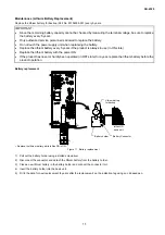
Page 11: ...he power ON If the product has never or hardly been operated in OFF state for a year replace the lithium battery before the product operation Battery replacement Replace the lithium battery while Infilex GD is ON Figure 11 Battery replacement 1 Pull out the battery holder using a slotted screwdriver 2 Disconnect the connector and detach the lithium battery from the battery holder 3 Place a new lit...

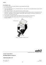
Page 12: ...urning on the power make sure that the wires are correctly connected Several tens of seconds are required for the product normal operation after the power is turned on During this time the red LED ERR1 major failure on the front lights up indicating major failure temporarily but this does not indicate an error Do not connect wires to vacant terminals Leave at least 35 mm clearance between the top ...

Reviews: