2
Important
•
All wiring and installation must comply with applicable
local electrical codes, ordinances and regulations.
•
Voltage and frequency of the power supply must match
the S720B being used.
•
Make sure the S720B is properly grounded.
Mounting
The S720B can be mounted in any position.
Fig. 3(page
4) for mounting hole locations. Ensure that enough space is
available to make the high voltage connections without difficulty.
Wiring
WARNING
Electrical Shock Hazard.
Can cause serious injury, death or property damage.
Disconnect power supply before beginning wiring
to prevent electrical shock and equipment damage.
More than one disconnect may be required.
(1) All wiring must comply with applicable UL regulations.
(2) Voltage and frequency of the power supply:
120 V AC, 60 Hz
(3) Be sure the mounting chassis of the S720B is properly
grounded.
NOTE: S720B power input wiring can be the following:
Connect the blue wire to the output terminal of your device
and the brown wire to L2.
Ignition (Secondary) Wiring
(1) Keep the secondary cable as short as possible to keep radio
frequency interference (RFI) to a minimum.
(2) If the high voltage cable is longer than 24 inches (610 mm),
modify it with insulating material in such a way that it
stays more than 2 inches (51 mm) away from the ground
terminal.
(3) Ignition cable connections may be either “Rajah” or screw
type. If screw connections are desired, simply loosen the
“Rajah” terminal.
(4) Use ignition cable rated for continuous duty at 350 °F
(177 °C) and 20,000 volts.
Cable in the Specifications section.
Important
•
The ignition cable should not exceed 40 inches (1 m) in
length.
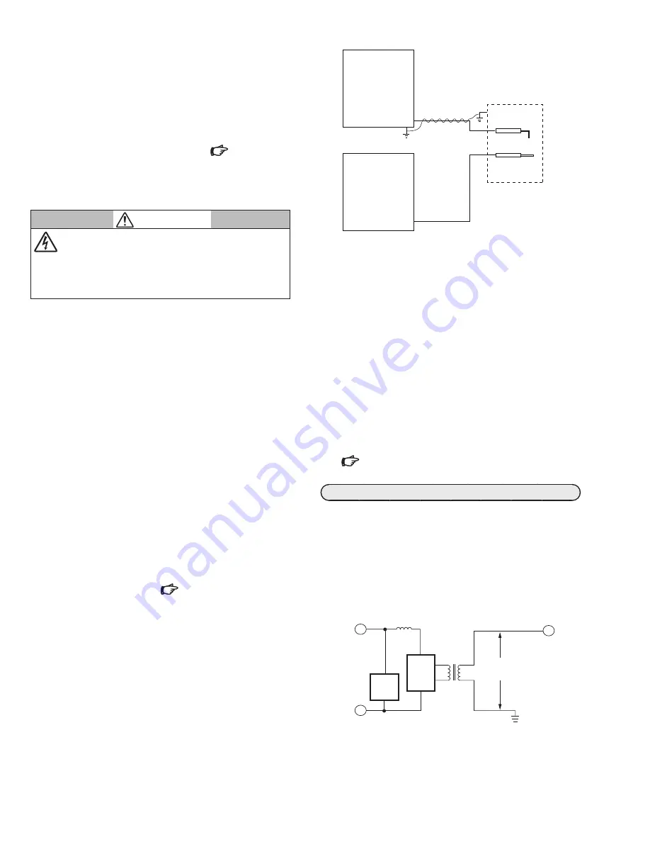
To ground the S720B to the burner assembly:
(1) Use 16 or 18 AWG wire.
(2) Attach one end of the wire to the S720B igniter end (GND).
(3) If required,wrap the wire around the igniter (high tension)
lead as shown in Fig. 1. Four or five wraps are sufficient.
(4) Connect the other end of the wire to the burner assembly
(GND).
(5) Make sure the ground connection between the S720B and
the burner body is secure.
IGNITER
Fig. 1. Grounding the S720B to the burner assembly.
IGNITION
LEAD
FLAME ROD
LEAD
BURNER ASSEMBLY
BURNER
CONTROLLER
Electrode Setting and Positioning
l
Gas Burner Systems
Ignition electrode location must be found by trial and error,
taking into account the following points:
(1) Ignition electrodes must not interfere with the normal
flame pattern.
(2) Ignition electrodes should not be positioned such that
they will be overheated by the flame.
(3) The flame detection device must not be adversely af-
fected. In the case of flame rod sensors make sure that the
ignition spark does not disturb the flame signal unduly.
For ultraviolet (UV) flame detectors, ensure that the spark does not
give a false flame indication.
Ignition Spark Response Test in the Checkout section.
OPERATION
Principles of Operation
Referring to Fig. 2, it can be seen that the S720B essentially com-
prises an RFI filter circuit, a solid state oscillator circuit and a
high voltage transformer. The solid state oscillator is comprised
of a transistor controlling an LC resonant circuit.
The capacitor in the LC circuit charges and discharges and the
voltage developed across the inductor is stepped up by the high
voltage transformer.
Fig. 2. Internal schematic of S720B Igniter.
SUPPLY
VOLTAGE
RFI
FILTER
CIRCUIT
SOLID
STATE
OSCIL-
LATOR
HIGH
VOLTAGE
TRANSFORMER
14 kV PEAK
OUTPUT
VOLTAGE


