AB-5702
7
Wiring
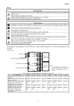
WARNING
Before detaching the terminal cover, be sure to turn off the power to the product. After wiring, be sure to reattach the
terminal cover.
Failure to do so might cause electric shock.
Before wiring and maintenance, be sure to turn off the power to the product.
Failure to do so might cause electric shock or device failure.
CAUTION
Installation and wiring must be performed by qualified personnel in accordance with all applicable safety standards.
All wiring must comply with applicable codes and ordinances.
Firmly tighten the terminal screws.
Insufficient tightening of the terminal screws might cause fire or overheating.
Do not use unused/spare terminals on the product as relay terminals.
Doing so might cause malfunction.
When replacing the battery, read the instructions hereinafter and correctly attach the new battery to the product.
Failure to do so might cause overheating, burst, or leakage of the battery.
Dispose of the used battery in accordance with your local regulations.
Do not throw it in fire or in general garbage.
Doing so might cause burst or ignition.
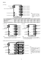
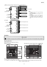
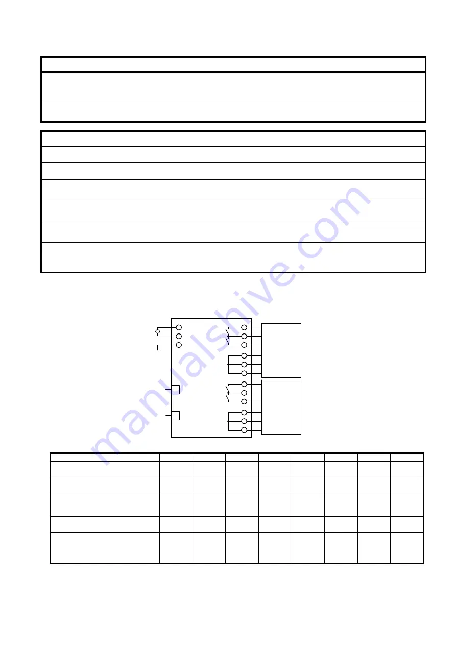
The following are wiring diagrams of each CDGP model. Note that these diagrams do not show the appropriate mounting
orientation.
●
DIO model
Point configurations and point assignment to the terminals: DIO model
Point configuration
DO1-1
DO1-2
DI1-1 DI1-2 DO2-1 DO2-2 DI2-1 DI2-2
Start/stop point (Maintained contact
output) x 2
ON/OFF 1 Not used
Not used
Not used
ON/OFF 2 Not used Not used
Not used
Start/stop, status point (Maintained
contact output ) x 2
ON/OFF 1 Not used
Status 1
Not used
ON/OFF 2 Not used Status 2
Not used
Start/stop, status point (Momentary
contact with/without
unmatched alarm monitoring) x 2
ON/OFF 1
(ON)
ON/OFF 1
(OFF)
Status 1
Not used
ON/OFF 2
(ON)
ON/OFF 2
(OFF)
Status 2
Not used
Start/stop, status, alarm point
(Maintained contact output) x 2
ON/OFF 1 Not used
Status 1
Alarm 1
ON/OFF 2 Not used Status 2
Alarm 2
Start/stop, status, alarm point
(Momentary contact
with/without unmatched alarm
monitoring) x 2
ON/OFF 1
(ON)
ON/OFF 1
(OFF)
Status 1
Alarm 1
ON/OFF 2
(ON)
ON/OFF 2
(OFF)
Status 2
Alarm 2
*
85–264 V AC
~
To another sub controller
Grounding
(Max. 100
Ω
ground resistance)
5
4
6
8
7
9
10
11
12
13
14
15
CDGP
2
1
3
SC-bus OUT
CN4
SC-bus IN
CN3
Device in
connection
Device in
connection
DO1-1
(ON output)
DO1-2
(OFF output)
DO2-1
(ON output)
To another sub controller
*
DI1-2
DO2-2
(OFF output)
DI2-1
DI2-2
DI1-1
Note:
* If the output of the device in
connection has polarity, connect 0 V
wire to the terminals 8 and 14 of
CDGP.

