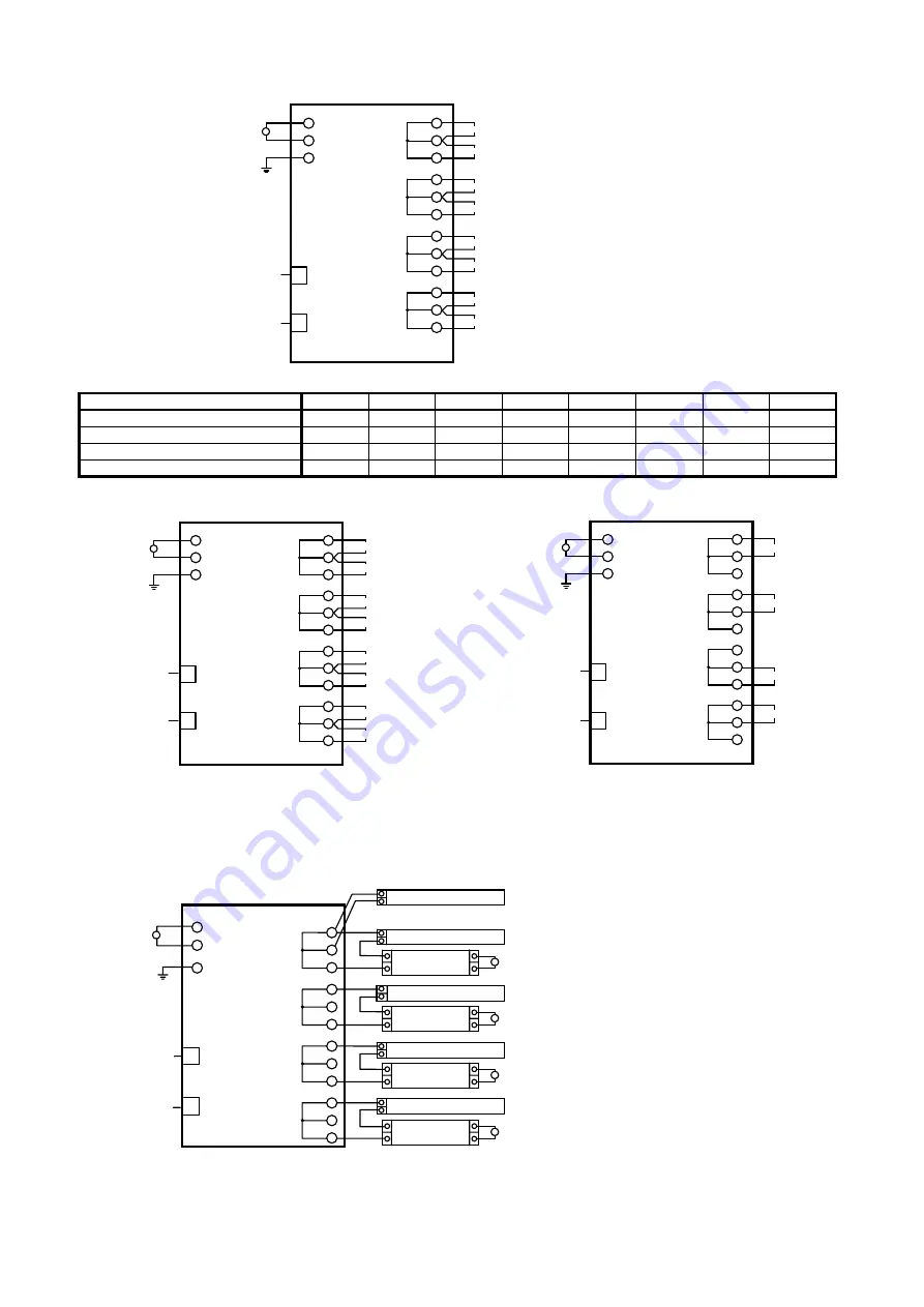
AB-5702
8
●
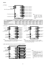
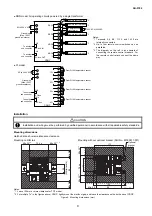
DI model
Point configurations and point assignment to the terminals: DI model
Point
configuration
DI1 DI2 DI3 DI4 DI5 DI6 DI7 DI8
Status, alarm point x 4
Status 1
Alarm 1
Status 2
Alarm 2
Status 3
Alarm 3
Status 4
Alarm 4
Status point x 8
Status 1
Status 2
Status 3
Status 4
Status 5
Status 6
Status 7
Status 8
Alarm point x 8
Alarm 1
Alarm 2
Alarm 3
Alarm 4
Alarm 5
Alarm 6
Alarm 7
Alarm 8
Status point x 4 + alarm point x 4
Status 1
Status 2
Status 3
Status 4
Alarm 1
Alarm 2
Alarm 3
Alarm 4
●
TOT
model
●
AI model
●
RRD model: Each operating circuit powered by separate transformer
DI7
DI8
DI5
DI6
DI3
DI4
85 to 264 V AC
~
To another sub controller
Grounding
(Max. 100
Ω
ground resistance)
5
4
6
*
DI1
8
7
9
10
11
12
13
14
15
CDGP
2
1
3
SC-bus OUT
CN4
SC-bus IN
CN3
To another sub controller
From device in connection
From device in connection
From device in connection
From device in connection
From device in connection
From device in connection
From device in connection
From device in connection
DI2
*
*
*
Note:
* If the output of the device in
connection has
polarity,
connect 0 V wire to the
terminals 5, 8, 11 and 14 of
CDGP.
*
*
*
~
To another
sub controller
Grounding
(Max. 100
Ω
ground resistance)
5
4
6
*
TOT1
8
7
9
10
11
12
13
14
15
CDGP
2
1
3
SC-bus OUT
CN4
SC-bus IN
CN3
TOT2
TOT3
TOT4
TOT5
TOT6
TOT7
TOT8
85 to 264 V AC
To another
sub controller
From device in
connection
From device in
connection
From device in
connection
From device in
connection
From device in
connection
From device in
connection
From device in
connection
From device in
connection
Note:
* If the output of the device in connection has polarity, connect 0 V
wire to the terminals 5, 8, 11 and 14 of CDGP.
~
5
4
6
*
1
1-5V
8
7
9
10
11
12
13
14
15
CDGP
2
1
3
4-20mA
AI1*
2
AI2*
2
AI3*
2
AI4*
2
SC-bus OUT
CN4
SC-bus IN
CN3
Grounding
(Max. 100
Ω
ground resistance)
85 to 264 V AC
To another
sub controller
To another
sub controller
*
1
1-5V
4-20mA
*
1
1-5V
4-20mA
*
1
1-5V
4-20mA
From device in
connection
From device in
connection
From device in
connection
From device in
connection
Notes:
*1 Connect 0 V wire to the terminals 5, 8, 11 and 14 of CDGP.
*2 AI1 to AI4 in the above diagram is an example of using 1-5 V of
AI1, AI2, AI4 and 4-20mA of AI3.
*2
White
Red
5
4
6
Remote control
transformer
Red
Blue
100V AC or 200V AC
Blue
*1
RRD1
White
8
7
9
Remote control breaker
Red
Blue
Blue
White
10
Red
Blue
Blue
White
Red
Blue
Blue
White
11
12
13
14
15
~
~
CDGP
2
1
3
CN4
CN3
To another
sub controller
Grounding
(Max. 100
Ω
ground resistance)
85 to 264 V AC
To another
sub controller
SC-bus OUT
SC-bus IN
*1
RRD2
*1
RRD3
*1
RRD4
Remote control switch
Remote control breaker
Remote control
transformer
100V AC or 200V AC
~
Remote control breaker
Remote control
transformer
100V AC or 200V AC
~
Remote control breaker
Remote control
transformer
100V AC or 200V AC
~
Notes:
*1 Terminals 5-6, 8-9, 11-12, and 14
-15 are internally connected.
*2 Up to four remote control switches
can be paralleled.
*3 The diagram on the left is an
example of connecting the remote
control breakers. For the remote
control relays, connect the same
way.
*3
*3
*3
*3

