Protocol - Modular AC-DSP
V1_version Feb-2011
5
2
CONNECTION AND PINOUT.
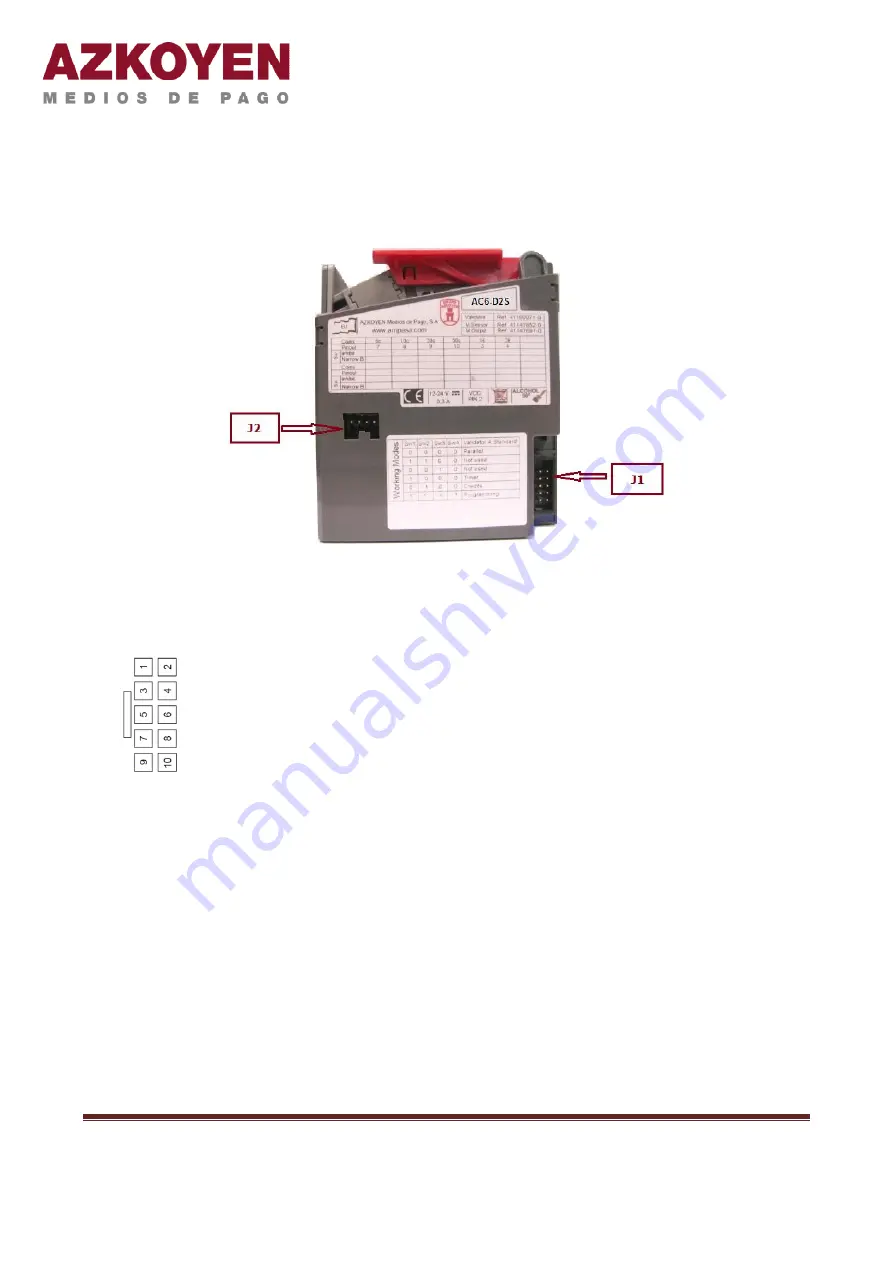
The validators AC-DSP have 2 connectors that are accessible to the user.
Figure 1. Connectors accessible to the user.
2.1
Connector J1 (10 pins) for communication with the machine.
It is the main connector for communication with the machine.
Power to the validator is through pins 1 (GND) and 2 (Vdc) for this
connector
The function of each of the pins will vary depending on the
operating mode selected by the user. See section 3 Operation for
details.
2.2
Connector J2 (4 pins) for the communication with the Azkoyen tools.
This 4-pin connector is used to connect the validator software tools (
HEUS
) and the Azkoyen
hardware interface (
TL20
).
Section 5 Tools, gives details on the procedure to follow for the connection of the validator
tools.
This connector pinout is detailed in the following table:


