10015UK 01 -2004
Technical information:
ES-525 Validator
21
5.
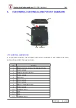
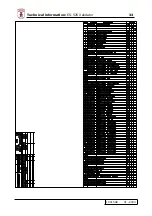
ELECTRONIC, ELECTRICAL AND PIN OUT DIAGRAMS
JP2
JP6
JP1
JP5
JP4
JP8
Switches
JP5: GENERAL CONNECTOR
A 17-pin male connector. The connector used for its connection is the: Molex 22-01-2175,
terminal Molex 4809C Tin/Lead or similar.
Pin
Function
1
Ident. pin. Coin 6 output in dedicated mode
2
Coin 5 output
3 Output
common=Vcoma
4
Coin 1 output
5 Not
used
6
Coin 2 output
7
Coin 3 output
8
Binary / dedicated mode
9
Coin 4 output
10
Inhibition line 4
11 Vdc.
12 Gnd.
13
Inhibition line 3
Summary of Contents for ES-525
Page 20: ...10015UK 01 2004 Technical information ES 525 Validator 19 CE...
Page 33: ...10015UK 01 2004 Technical information ES 525 Validator 32 CPU Sel ES525 UK...
Page 34: ...10015UK 01 2004 Technical information ES 525 Validator 33...
Page 40: ...10015UK 01 2004 Technical information ES 525 Validator 39...

