


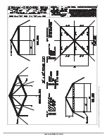


www.aztectent.com
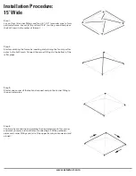
Step 9:
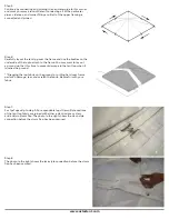
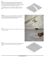
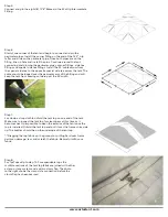
Lay down a drop cloth to unfold the tent top on one end of the tent.
Make sure to inspect the tent top for cleanliness at this time as it
becomes next to impossible to clean the exterior of the tent once the
top is installed. Unfold the tent top and pull it over the frame shiny side
up. The buckles should be on the underside of the tent top.
**Dragging the top fabric on the ground, or pulling hard over frame
parts can damage, tear, and scratch the fabric. Be careful with your
fabric.
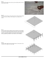
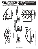
Step 10:
For 1pc Tops skip to step 12. For expandable tops the multiple sections
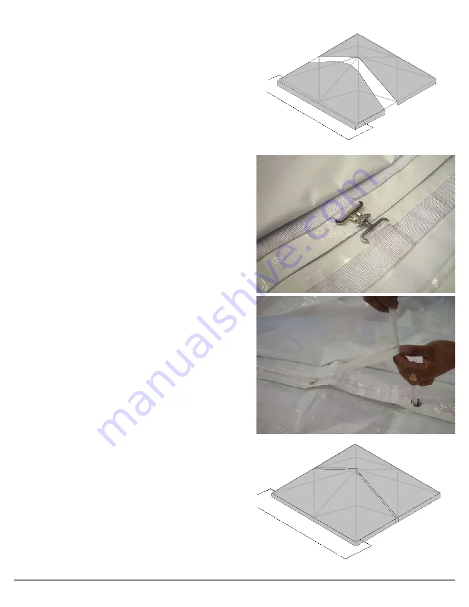
of the tent top fabric are joined with either a clasp or lace system
and a velcro storm fl ap. The photo to the right shows the clasp style
connection before the storm fl ap has been secured.
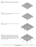
Step 11:
The photo to the right shows the lace style connection before the storm
fl ap has been secured.
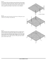
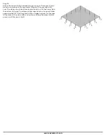
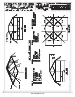
Step 12:
Now secure the tent top to the perimeter frame. Tighten the two buckles
closest to the corner fi tting fi rst then tighten the remainder of the
buckles.
Summary of Contents for STANDARD FRAME
Page 1: ...STANDARD FRAME PRODUCT MANUAL If YOU can IMAGINE it WE can BUILD it...
Page 27: ...www aztectent com...
Page 43: ......


