background image

www.aztectent.com

General Hardware Care & Maintenance

The hardware components developed for this tent system requires specifi c attention during installation, cleaning, and storage to 
maintain its maximum life span. Please follow the following care and maintenance guidelines provided for this product.

OXIDATION: The hardware components for this tent system have been supplied to you with specialty coatings to help limit oxidation. 
With usage, these coatings will need to be maintained in order to limit oxidation and for the product reach its full intended lifespan. 
With plated or powder coated steel components, any rust should be removed immediately with a stiff wire brush and sprayed with 
either a galvanizing spray or durable paint to seal the steel from the elements. Anodized aluminum components will get scratched over 
time and these scratched areas can develop a thin black oxidation common with mill fi nish aluminum. This black oxidation can cause 
staining to any fabric components that come in contact with the pole/component. Your best preventative measure will be to avoid 
scratching of the anodized coating by avoiding any sharp edges that might be come in contact with the aluminum member. 

HARDWARE CLEANING: It is very important to keep your hardware components clean and free of dirt, oxidation, and other chemicals 
especially if those hardware components come into contact with any fabric components during installation, use, or take-down of your 
product. Any dirt, oxidation, or chemical on the surface of the hardware member can transfer the contaminant to the fabric causing 
permanent staining, or permanent damage to the fabric membrane. If hardware components are found to be soiled, wipe down 
immediately to remove the foreign matter.

STORAGE RECOMMENDATIONS: The hardware for the tent system shall be stored dry in a cool, dry place. Anodized aluminum 
component can be stored outside, but should be covered to prevent foreign matter from collecting on the components that might stain 
or damage the fabric membrane during installation or use. Any/all steel components shall be stored indoors in a dry/low humidity 
environment. 

INSPECTION: Prior to and after each use, each component of the tent system needs to be thoroughly inspected to assure its structural 
stability has not been compromised. Hardware components that are bent, cracked, frayed, or damaged shall be immediately replaced 
and not used. Specifi c attention should be paid toward any devices used for anchoring including ratchets, ropes, cables, and web 
straps. 

Fabric Flame Retardancy

All vinyl fabric used in the production of our tents, walls, and accessories are certifi ed fl ame retardant per NFPA 701 and the California 
State Fire Marshal. These vinyl products are produced so that they are inherently fl ame retardant, and thus will never require additional 
applications of fl ame retardant chemicals.

Every section of fabric produced by Aztec Tents contains a label identifying its fl ame resistance characteristics and date produced. This 
label matches a hard copy of the fl ame certifi cate that is mailed to you after receipt of your goods. 

If at any time you need to be issued a duplicate fl ame certifi cate, you can request one from our customer service representatives. 
Please be sure to have the invoice number and date of production available when requesting duplicate fl ame certifi cates.

Anchoring

All anchoring locations must be laid out accurately as described in the manual and diagrams contained within (in advance of laying 
out the fabric) to a tolerance of +/_ 4” in any direction (right or left, forward or back, up or down, etc.) All column base locations must 
be laid out to a tolerance of +/- 3” in any direction for any standard supported tents and within a tolerance of +/-.5” for any product 
utilizing keder channels.

A wide variety of ground anchoring devices are commonly used. Soil conditions and resulting ground anchor holding capacities vary 
from site to site, and can vary within a particular site. The Owner and/or Installer of the tent is fully responsible for assuring that the 
selection and installation of the anchoring devices is adequate to resist the pull out loads specifi ed in the product manual. 

Reduced anchor performance can occur under wet soil conditions and needs to be accounted for. Care should be taken that water is not 
allowed to drain or collect near anchors.

Anchoring device holding capacity can be developed using a single large device, or by using multiple smaller devices.

Ensure that the anchors installed are adequate to resist the pull out loads shown. Actual testing of some individual anchors to 75% of 
the anchor pull-out load is recommended.

Additional installation and anchoring information entitled “The IFAI Procedural Handbook For The Safe Installation And Maintenance Of 
Tentage” is published by the Tent Rental Division of the Industrial Fabric Association International (IFAI).

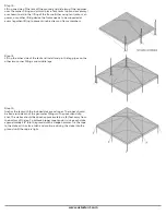
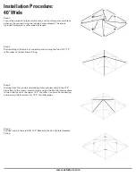
Summary of Contents for STANDARD FRAME

Page 1: ...STANDARD FRAME PRODUCT MANUAL If YOU can IMAGINE it WE can BUILD it...

Page 2: ...e tent The installation of electrical plumbing lighting appliances and or HVAC equipment are not covered within this manual Users Installers shall follow local code requirements for the installation o...

Page 3: ...e 4 General Hardware Care Maintenance 5 Fabric Flame Retardant Information 5 Anchoring 5 Pre Installation Guidelines 6 General Installation Guidelines 6 Post Installation Guidelines Maintenance 6 Safe...

Page 4: ...amount of water placed on the fabric to expedite drying time Never allow the tent cleaner to dry on the fabric For this reason larger tents might be better to clean in sections Once the cleaning is co...

Page 5: ...e bent cracked frayed or damaged shall be immediately replaced and not used Speci c attention should be paid toward any devices used for anchoring including ratchets ropes cables and web straps Fabric...

Page 6: ...stretch mast base settling changes to design geometry etc Changes to the design geometry of the tent and consequently the structural performance characteristics of the tent can occur while the tent i...

Page 7: ...he same procedures outlined but in the reverse order Once unassembled each component of the system should be inspected for any signs of visual damage by the installer All damaged materials should be m...

Page 8: ...stallation tool Utility Knife General installation tool Tape Measure General installation tool Marking Paint Chalk Used to mark anchoring locations and tent boundaries Optional Items Accessories Avail...

Page 9: ...of the tent Step 2 Start assembling the frame by inserting and pinning the four hip rafter poles to the 4pt Crown Connect the corner ttings to the bottom of the rafter pipes Step 3 Start at one corne...

Page 10: ...he leg pipes over the corner tting and pin into place Step 7 Lift up the other side of the tent and install and pin the leg pipes on the other two corner ttings Step 8 Anchor the tent with the include...

Page 11: ...e frame by inserting and pinning the four hip rafter poles to the 4pt Crown Connect the corner ttings to the bottom of the rafter pipes Step 3 Start at one corner of the tent and connect and pin the c...

Page 12: ...bric Step 6 Lift up one side of the tent off the ground and slide two of the leg pipes over the corner tting and pin into place Step 7 Lift up the other side of the tent and install and pin the leg pi...

Page 13: ...nd and place the 8pt Crown in the center of the tent Step 2 Start assembling the frame by inserting and pinning the four hip rafter poles to the 8pt Crown Connect the corner ttings to the bottom of th...

Page 14: ...out a ground cloth at this time to prevent damage to the tent top when it touches the ground Dragging the top fabric on the ground or pulling hard over frame parts can damage tear and scratch the fab...

Page 15: ...f the tent and install and pin the leg pipes on the other two corner ttings Step 12 Anchor the tent with the included stakes and ropes The ropes should be tied around each of the perimeter ttings with...

Page 16: ...ncluded diagram Lay out the corner ttings special side tee ttings and crown tting on the ground Step 2 Connect and pin the four 4 21 10 hip rafter poles to the 8pt crown Step 3 Connect and pin the fou...

Page 17: ...ross the tent The cable should be looped over the perimeter arm of the tting and will keep the tent from bowing outward past the 30 width Step 8 Start at one corner of the tent and begin to connect an...

Page 18: ...ling hard over frame parts can damage tear and scratch the fabric Be careful with your fabric Step 10 For 1pcTops skip to step 12 For expandable tops the multiple sections of the tent top fabric are j...

Page 19: ...Step 14 Lift up the other side of the tent and install and pin the leg pipes on the other two corner ttings and middle legs Step 15 Anchor the tent with the included stakes and ropes The ropes should...

Page 20: ...t building the frame by connecting and pinning the four 4 21 10 rafter pipes to the 8pt Crown tting Step 3 Starting from the crown and working down connect and pin the 14 4 hip rafters to the Crown No...

Page 21: ...rm of the tting and will keep the tent from bowing outward past the 40 width Step 7 Lay down a drop cloth to unfold the tent top on one end of the tent Make sure to inspect the tent top for cleanlines...

Page 22: ...1 Lift up one side of the tent off the ground and slide two of the leg pipes over the corner tting and pin into place Tent Jacks optional accessory are shown to aid in the lifting of the frame Either...

Page 23: ...ngs with an overhand slip knot The stakes should be driven approximately six 6 feet away from the bottom of the leg To achieve proper rope tension drive each stake approximately 38 into the ground wit...

Page 24: ...www aztectent com K cad files Frame Tents DIAGRAMS 10x 10x10 dwg 2 28 2007 9 59 16 AM pdfFactory pc3...

Page 25: ...www aztectent com K cad files Frame Tents DIAGRAMS 10x 10x20 dwg 2 28 2007 10 07 28 AM pdfFactory pc3...

Page 26: ...www aztectent com K cad files Frame Tents DIAGRAMS 15x 15x15 dwg 4 2 2007 5 43 29 PM pdfFactory pc3...

Page 27: ...www aztectent com...

Page 28: ...www aztectent com K cad files Frame Tents DIAGRAMS 20x 20x20 dwg 2 14 2007 3 45 09 PM pdfFactory pc3...

Page 29: ...www aztectent com K cad files Frame Tents DIAGRAMS 20x 20x30 dwg 2 14 2007 3 50 25 PM pdfFactory pc3...

Page 30: ...www aztectent com K cad files Frame Tents DIAGRAMS 30x 30x30 dwg 2 9 2007 9 12 23 AM pdfFactory pc3...

Page 31: ...www aztectent com K cad files Frame Tents DIAGRAMS 30x 30x40 dwg 2 14 2007 5 51 58 PM pdfFactory pc3...

Page 32: ...www aztectent com K cad files Frame Tents DIAGRAMS 30x 30x60 15 dwg 2 15 2007 5 06 02 PM pdfFactory pc3...

Page 33: ...www aztectent com K cad files Frame Tents DIAGRAMS 30x 30x80 dwg 2 16 2007 1 55 26 PM pdfFactory pc3...

Page 34: ...www aztectent com K cad files Frame Tents DIAGRAMS 40x 40x40 dwg 7 13 2006 3 57 50 PM pdfFactory pc3...

Page 35: ...www aztectent com K cad files Frame Tents DIAGRAMS 40x 40x60 dwg 2 16 2007 5 45 38 PM pdfFactory pc3...

Page 36: ...www aztectent com K cad files Frame Tents DIAGRAMS 40x 40x80 dwg 2 22 2007 1 38 56 PM pdfFactory pc3...

Page 37: ...www aztectent com K cad files Frame Tents DIAGRAMS 40x 40x100 dwg 2 22 2007 3 00 26 PM pdfFactory pc3...

Page 38: ...Right Gable Corner Left Gable Crown 3pt Gable Crown 4pt 2 Slide Fitting Add Leg Qwik Corner 3 Way Crown 4 Way Crown 6 Way Crown 8 Way Crown Hip Intermediate 40x Hip Slide Intermediate 30x Rafter Slid...

Page 39: ...adapin Assembly Pin Jumbo Pin 2 Adjustable Qwik Baseplate Standard Baseplate Standard Baseplate 2 Adjustable Qwik Footplate 1 2 Polopro x 18 Rope 2 Slide Bally Corner Fitting 2 RoundTubing Extrusion S...

Page 40: ...t the loads below The below chart lists the required resistance loads that must be supported by the anchoring system to meet the engineering loads speci ed under the code A Factor of Safety of 2 0 tim...

Page 41: ...CTUAL LOAD VALUE Standard Frame Load Summary 30 Width UPLIFT SHEAR BEARING LOAD OUT OF PLANE SHEAR IN PLANE SHEAR TENSION UPLIFT SAMPLE ACTUAL LOAD VALUE MINIMUM DESIGN LOAD FOR ANCHORING SYSTEM MINIM...

Page 42: ...299F00110 Z299F00120 Z299F00130 Z299F00140 Z299F00145 Z299F00150 Z299F00160 Z299F00170 Z299F00180 Z299F00190 Z299F00195 Z299F00200 Z299F00220 1 10 x 2 Pipe 2 8 x 2 Pipe 3 4 2 Pipe 3 10 2 Pipe 4 4 2 Pi...

Page 43: ......

Reviews: