OPERATION MANUAL
Technical changes reserved
0141 0316-25 08.02.2021
USB-I²C-adapter
for B+B Temperature-module with I²C-output
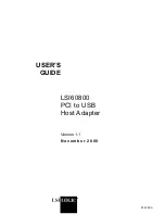
Now, in order to fetch further measured values, every time you will have to
enter:
IR_78004 <CR>
Each time the USB-module replies with the current measured values.
Interpretation of values
The left four hex numbers are the first channel (e.g. humidity or pressure) and
the following four hex numbers are the values of second channel, usually for
the temperature of the module, if used.
Conversion of measured values
The following example refers to the
Humidity-Temperature module
and the
transmitted string ‚3EEF4499 ‚ in the answer:
The front four digits ‚3EEF‘ are the humidity value, the following digits ‚4499‘
are for the temperature value in hexadecimal format.
Now, first the
Humidity value
is converted from HEX to decimal (in example
16111) and then divided by 327,68 as per the data sheet. On
rounding the two post comma places, the humidity value in decimal format
comes out as 49.17 % RH.
The
Temperature value
is also first converted into decimal (17561) and then
divided by 256 as per data sheet and 32 is subtracted from the result.
After rounding off the two post comma places, it results in the temperature
value of 36.60 °C.
With the other modules under consideration. One has to proceed in the same
way as per data sheet.
For further information, visit our website:
www.bb-sensors.com
Module
Channel 1
Channel 2
Humidity module
rel. humidity
un-calibrated
Feuchte-
Humidity-Temp. module
rel. humidity
Temperature
PT1000
PT1000 Temp. module
PT1000
Temperature
un-calibrated
Thermoelemente
Thermo element
Temp. module
Thermovoltage
Temperature
calibration point
Pressure module
Pressure
un-calibrated
Command overview for examples
The USB-adapter has a very extensive command set. Detailed description is
available on the enclosed CD. The following explanations are only related to
the commands used in the above examples:
‚V‘ Statement of version string
This command responds back with the version string of the controller Firm-
ware.
‚T11200‘ Initialising
Definition of operating voltage and the time delay before the first communi
-
cation. This command must be sent before the first I²C communication takes
place. The last 3 digits are for the time delay after switching on the operating
voltage and before the first reading of measured value.
‚IRT78004‘ I²C Read with on-timing
This command switches on the operating voltage, waits for the time delay as
defined in the initialising sequence and then finishes reading over I²C at the
address stated in the ASIC.
The first two digits (78) are the 7-bit I²C address of the ASIC. The following 3
digits (in example 004) determines the number of digits to be read.
The ASIC always responds to the address 78, however it can also be program-
med at another address, so that it is possible to operate several ASICs at the
same I²C-Bus.
The time delay enables the ASIC to carry out a measurement after feeding the
operating voltage,
before the measured values are read out first time.
The operating voltage remains switched on even afterwards. Hence, the IRT
command is required only for the first time to switch on the operating voltage.
‚IR_78004‘ I²C read
This command is identical to the previous one, however without switch on of
the operating voltage and without time delay.
This I²C-read command is used for all further read operations in response.
B+B Thermo-Technik GmbH | Heinrich-Hertz-Straße 4 | D-78166 Donaueschingen
Fon +49 771 83160 | Fax +49 771 831650 | info@bb-sensors.com | bb-sensors.com
3 / 4