background image


AirborneM2M™ User Guide


60 

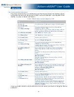
CONFIGURING SERIAL PORT 2 FOR ACCESS ON TUNNEL PORT 

A data tunnel can be made using the device’s tunnel port as the network connection port. This does not 

require authenticating with the device and automatically initiates the tunnel connection. Configuring the 

device to support this approach to establishing a data tunnel is covered in the following table. 

Table 35 – Configure Data Tunnel on Serial Port 2 Tunnel Port (TCP) 

Step 

Description 

Navigation Bar  

Select 

Configuration


You will see a group of fields under the banner of WLAN 

Parameters. 

Feature Link 

Select 

Connection Settings


The wireless interface and security must be configured before 

configuring the Ethernet settings. 
A page showing the configuration options for TCP/IP and UDP 

connections to the device. Configuration of Telnet, HTTP and 

SSH ports is possible through this page. 

Select 

Tunnel Enabled – Serial Port 2

  Select 

Enabled

Select 

Tunnel Port – Serial Port 2


Enter the port to be used for the tunnel. 
Default is 

8024

. This should only be changed if a port is already 

defined for the application server or it is already being used by 

another service. 

Select 

Tunnel Mode – Serial Port 2


Select 

TCP

 from drop down menu. 

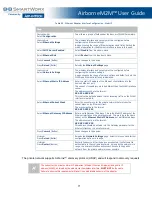
Press 

Commit

 [Button] 

Saves changes to the device. 

Press 

Reload

 [Button] 

Reloads the 

Connection Settings

 page.  

Feature Link 

Select 

Serial Port 2 Settings


The wireless interface and security must be configured before 

configuring the Ethernet settings. 
Displays a page showing the serial port configuration. Setting the 

default mode of operation for the serial interface is done in this 

page. 

Select 

Serial CLI Default Mode


Select 

Listen

 from the drop down menu. 

Press 

Commit

 [Button] 

Saves changes to the device. 

Optional 

Press 

Reload

 [Button] 

Reloads the 

Serial Port 2 Settings

 page. Select this is you 

have further configuration options to change. 

Optional 

Press 

Restart

 [Button] 

Restarts the device. After the device as rebooted, it will attempt 

to authenticate to the configured network. As long as the 

network is in range, the wireless interface will connect. 
Once authenticated to the network, it is possible for a TCP/IP 

connection to be made on the Telnet port. 

 
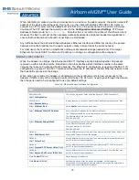
To establish a data tunnel and gain access to the serial data from the WLAN or Ethernet interface, follow 

the steps in Table 36. 

Table 36 - Data Tunnel using Tunnel Port on Serial Port 2 

Step 

Description 

Open TCP socket to device 

Using the WLAN IP Address and configured tunnel port number 

for Serial Port 2 (Default 8024). 


Summary of Contents for Airborne M2M ABDN-er-DP55 Series

Page 1: ...Airborne M2M USER MANUAL ABDN er se DP55x series ABDN er se IN5xxx series _Revision 1 3 _September 2018...

Page 2: ...L 61350 USA Phone 815 433 5100 Fax 815 433 5105 Advantech B B SmartWorx European Headquarters Westlink Commercial Park Oranmore Co Galway Ireland Phone 353 91 792444 Fax 353 91 792445 www advantech bb...

Page 3: ...cteristics Transmitter 21 Performance Range 21 Antenna 22 Antenna Selection 22 Host Board Mounted Antenna 22 Host Chassis Mounted Antenna 23 Embedded Antenna 23 Antenna Location 24 Performance 24 Mech...

Page 4: ...Tunnel Port 59 Configuring Serial Port 2 for Access on Tunnel Port 60 Configuring Serial Port 1 as TCP Client 61 Configuring Serial Port 2 as TCP Client 62 Installing and Using the Airborne VirtualCOM...

Page 5: ...Environmental Approvals 120 Figures Figure 1 Enterprise AirborneM2M Device 10 Figure 2 Industrial AirborneM2M Device 11 Figure 3 ABDx ER DP5xx Block Diagram 12 Figure 4 ABDx ER SE IN5xxx Block Diagram...

Page 6: ...49 Table 24 Configuring for WPA Security 50 Table 25 Configuring for WPA2 Security 51 Table 26 Configuring for PEAP Security 52 Table 27 Configuring DHCP WLAN 53 Table 28 Configuring DHCP Ethernet 54...

Page 7: ...special attention The below convention will be used The area next to the indicator will identify the specific information and make any references necessary The area next to the indicator will identif...

Page 8: ...station and devices were directly attached through a serial port The AirborneM2M Ethernet Adapter provides a link between the 802 11 wireless LAN and any Ethernet ready device with an RJ 45 connector...

Page 9: ...rt Forwarding Ethernet FTP Server Supports flexible antenna selection Operating Temperature 40 to 85 C Storage Temperature 40 to 85 C Industry standard wired connections DB 9 Serial Connectors RS 232...

Page 10: ...ion to the Ethernet port of the host is made via an RJ 45 socket or pigtail with an RJ 45 plug The device supports a 10 100 Ethernet interface with auto configuration Manual control of the interface i...

Page 11: ...product class supports the full industrial operating temperature range and the complete set of functional capabilities of the Airborne Device Server and Wireless Adapter technology Figure 2 Industrial...

Page 12: ...AirborneM2M User Guide 12 BLOCK DIAGRAMS The following outlines the block diagram for the devices Figure 3 ABDN ER DP55x Block Diagram...

Page 13: ...e selected The following defines the pin outs for the individual interfaces SERIAL PORTS The AirborneM2M units support either a single or dual serial port configuration The port pin out can change dep...

Page 14: ...pin 9 only available on Enterprise devices ABDN xx DP551 3 Only required on Industrial products ABDN xx IN54xx Table 2 shows the availability of the serial ports and available interface types by produ...

Page 15: ...supported Table 3a Figure 6 Ethernet Jack Pin Out Table 3 Ethernet Connector Pin Out Pin RJ45 Socket Industrial RJ45 Plug Enterprise 1 TxD RxD 2 TxD RxD 3 RxD TxD 4 NC NC 5 NC NC 6 RxD TxD 7 NC NC 8 N...

Page 16: ...lost the ability to communicate on any of the available ports preventing access to one of the configuration interfaces and blocking your ability to recover the device by correcting the configuration...

Page 17: ...ype selected by the interface jumpers in Figure 7 must match the selected configuration for the Configuration Serial Port Settings Serial Interface Type setting in the web interface INDICATOR LEDS The...

Page 18: ...lished On WLAN or Ethernet interface A physical Serial Ethernet connection has been detected A TCP connection to the adapter has been established from the WLAN or Ethernet interface but no traffic has...

Page 19: ...eter Rate Mb s Min Average dBm mW Peak dBm mW Units POUTB Transmit Power Output 802 11b 11 5 5 2 1 15 0 31 6 dBm POUTG Transmit Power Output 802 11g 6 9 12 18 24 36 48 54 12 6 18 2 dBm POUTA Transmit...

Page 20: ...S Canada 2 401 2 473 11 1 11 Europe 2 401 2 483 13 1 13 802 11g1 2 US Canada 2 401 2 473 11 1 11 Europe 2 401 2 483 13 1 13 802 11a2 US Canada 5 15 5 35 5 725 5 825 13 36 40 44 48 52 56 60 64 149 153...

Page 21: ...Range Data Rate Typical Outdoor Distance Unity gain antenna Typical Outdoor Distance 2dBi antenna gain on each end for B G mode 1 0 Mb s 240m 380m 11 0 Mb s 135m 215m 6Mb s 802 11g 135m 215m 6Mb s 80...

Page 22: ...edded antenna In addition to the above options location and performance need to be considered The following sections discuss these items HOST BOARD MOUNTED ANTENNA Host board mounted requires that an...

Page 23: ...the embedded options will in most cases be less than that achievable with external antenna This does not make them unusable but it will impact choice of antenna type and requires more focus on placem...

Page 24: ...pment as possible Locate the antenna where there is a minimum obstruction between the antenna and the location of the access points Typically access points are located in the ceiling or high on walls...

Page 25: ...er of other things that contribute to the link quality These include items discussed earlier and choices made when looking at the overall antenna gain The antenna gain contributes to the Equivalent Is...

Page 26: ...e Polarity SMA Requires 2 4GHz 5GHz ISM band antenna 50 input impedance RP SMA connector Serial Connector DB 9M Male Requires DB 9 female Ethernet Connector RJ 45 Plug Requires RJ 45 socket 10 100 Eth...

Page 27: ...14mm 4 65 120 12mm 4 73 29 21mm 1 15 124 14mm 4 89 94 72mm 3 73 CONNECT LINK POST POWER Antenna Connector RP SMA Reverse Polarity SMA Requires 2 4GHz 5GHz ISM band antenna 50 input impedance RP SMA co...

Page 28: ...ur own power supply ensure the correct power connector type and polarity are being used Verify the appropriate voltage to be applied by checking Table 8 for the correct product class Confirm the devic...

Page 29: ...borne folder located in the programs directory of your system When the application opens the following dialog will be displayed Select Group Name manuf and enter Group Password dpac 7 The AMC will loa...

Page 30: ...ces status will move to managed and the device will be displayed under the device type group it belongs to Right click the device and then 1 Select Connectivity Tools 2 Select Launch Web Browser for O...

Page 31: ...16 0 to continue set up of the device If this is not the first time proceed to section to update configuration 12 When the Reboot button is pressed the unit will restart and install new settings This...

Page 32: ...appropriate device software and documentation 3 Connect the Ethernet cable on ABDx to an Ethernet port on the laptop or desktop system 4 Apply power to the ABDx ER DP5xx IN5xxx 5 The unit will boot an...

Page 33: ...ttached device If the unit is not detected please verify that your firewall is disabled Run a Discover If the unit is still not being detected close down AMC and restart it by doing a Right click on t...

Page 34: ...1 Right click the device or select multiple devices first then right click a device 2 Select Template Management 3 Select Select Device Configuration Template 4 Select the correct bridge template Onc...

Page 35: ...erent operations that can be performed by the AirborneM2M device See section 15 0 for a full description of how to use the web interface 12 Using Express Setup If this is the first time you have confi...

Page 36: ...eb interface follow the steps outlined in section 14 0 to establish the IP address of the module Once the IP address is known open a web browser and enter the IP address of the module in the URL windo...

Page 37: ...for delivery of OEM and user configuration files as well as management and viewing of current configurations Certificates This menu item provides the interface for certificate delivery and management...

Page 38: ...ice selections The Feature Links are located in the left hand panel of the web page see Figure 11 Figure 11 Feature Links NAVIGATING THE WEBSITE A standard web page looks like Figure 12 The navigation...

Page 39: ...button Then either type in the appropriate content or select from the pull down menu Once you have finished modifying parameters scroll to the bottom of the page and press the Commit button The page...

Page 40: ...d window and will have entered the location and file name of the certificate you want to upload in the field next to the Browse button Press Upload Certificate You will then see a notice that the cert...

Page 41: ...e Press List Configuration Files This will show the current configuration files resident on the module and will include the file just uploaded UPDATING FIRMWARE The module s firmware may be updated us...

Page 42: ...AirborneM2M User Guide 42 Figure 15 Firmware Update Page Figure 16 Firmware Update in Progress...

Page 43: ...the module Select the firmware image file and press Open This will return you to the Upload Firmware window and will have entered the location and file name of the firmware image that you want to upl...

Page 44: ...gle location For more advanced configurations the full set of options are available in the feature links left hand column The Express Setup web page will display the necessary fields based on the sele...

Page 45: ...network you want to access This field is case sensitive Select Wireless LAN Security Type Select the security type the wireless network you want to access is using Depending on the option you choose...

Page 46: ...by the Ethernet interface When configured as a serial device server Ethernet interface is in client mode this mask is only used if the Ethernet DHCP is disabled or DHCP failed Default 192 168 2 1 Pre...

Page 47: ...Link Select WLAN Settings This step is optional The default home page for the Configuration link in the Navigation Bar is WLAN Settings Select Radio Startup Mode Select On from the drop down list Sel...

Page 48: ...ear i e one which has no other 802 11 network using it It is not necessary for all devices in a single AdHoc network to have the same channel number selected Select SSID Enter the name of the wireless...

Page 49: ...anged Only modify if you have been specifically told to by the network administrator Select Default WEP Key Select the key number that matches the selection used by the AP s in the wireless network Th...

Page 50: ...is case sensitive and must be entered exactly as it is in the AP The PSK cannot include spaces Press Commit Button Saves changes to the device Optional Press Reload Button Reloads the WLAN Settings p...

Page 51: ...nclude spaces Press Commit Button Saves changes to the device Optional Press Reload Button Reloads the WLAN Settings page Select this if you have further configuration options to change Optional Press...

Page 52: ...Enter the RADIUS server account password for the EAP Ident Select EAP Phase 1 String Enter peaplabel 0 Select EAP Phase 1 String Enter auth MSCHAPV2 Select CA Certificate Filename Enter the name of t...

Page 53: ...disabled on the WLAN interface It requires that there is a DHCP server on the WLAN network that the device has authenticated to and that the necessary network policies will allow the server to lease...

Page 54: ...mmit Button Saves changes to the device Press Reload Button Reloads the Ethernet Settings page Feature Link Select Network Settings The wireless interface and security must be configured before config...

Page 55: ...ble from the drop down menu Select WLAN Static IP Address Enter the assigned static IP address The address must be in the format XXX XXX XXX XXX Select Subnet Mask Enter the subnet mask for the networ...

Page 56: ...utton Reloads the Ethernet Settings page Feature Link Select Network Settings The wireless interface and security must be configured before configuring the network settings A page showing the range of...

Page 57: ...and manually initiating the tunnel connection Configuring the device to support this approach to establishing a data tunnel is covered in the following table Table 31 Configure Data Tunnel on Telnet P...

Page 58: ...he WLAN or Ethernet interface follow the steps in Table 32 Table 32 Data Tunnel using Telnet Port Step Description Open TCP socket to device Using the WLAN IP Address and configured telnet port number...

Page 59: ...elect Tunnel Mode Select TCP from drop down menu Press Commit Button Saves changes to the device Press Reload Button Reloads the Connection Settings page Feature Link Select Serial Port Settings The w...

Page 60: ...ice Select Tunnel Mode Serial Port 2 Select TCP from drop down menu Press Commit Button Saves changes to the device Press Reload Button Reloads the Connection Settings page Feature Link Select Serial...

Page 61: ...the IP address of the primary target server The address must be in the format XXX XXX XXX XXX Optional Select Secondary TCP Target Server IP Address Enter the IP address of the secondary target server...

Page 62: ...erial Port 2 Enter the IP address of the primary target server The address must be in the format XXX XXX XXX XXX Optional Select Secondary TCP Target Server IP Address Serial Port 2 Enter the IP addre...

Page 63: ...he VCOM driver for a specific device Once installed the host system will have additional COM ports by which the system may communicate with the device attached to the serial port on the Airborne devic...

Page 64: ...tall VCOM Driver for OEM Cfg1 Note if the port selection box does not have any ports listed cancel the install close AMC then restart AMC by right clicking the icon and clicking Run as administrator 5...

Page 65: ...that if your unit is a dual serial port device two VCOM ports will have been created 10 To identify which VCOM port is assigned to which device right click the Ethernet Serial Port and select Propert...

Page 66: ...s the Reload Button Navigation Bar Select Configuration You will see a group of fields under the banner of Interface and Network Parameters Feature Link Select Serial Port Settings The wireless interf...

Page 67: ...ected to from the drop down list This is only required if software flow control has been selected Select Serial CLI Default Mode Select Pass from the drop down menu Press Commit Button Saves changes t...

Page 68: ...f modifying network address information in datagram packet headers while in transit across a traffic routing device for the purpose of remapping a given address space into another In the case of a NAT...

Page 69: ...telnet or FTP access should be forwarded to the private network or handled by the Airborne Bridge Plug n Play In most cases all that is required for full functionality is configuration of the wireles...

Page 70: ...valid IP address This address will be the first IP address leased If more than one is leased they will increment from this address The subnet of the address must be different than the WLAN interface...

Page 71: ...coming traffic on the WLAN interface is routed to Select Ethernet Subnet Mask Enter the subnet mask for the private network that matches the subnet mask on the Ethernet client The mask must be in the...

Page 72: ...e configured ports for remote access to the Adapter If traffic to any of the configured ports http telnet ftp ssh etc need to pass through the module then the ports need to be reconfigured to use non...

Page 73: ...ning will cause the WLAN module to adopt the MAC address of the first Ethernet client that it sees traffic from If the Ethernet client uses DHCP the module will sniff the DHCP transactions and learn t...

Page 74: ...des a reference to the associated CLI command For further explanation of each of the fields please refer to the referenced command in the table see also Airborne Enterprise Command Line Reference Manu...

Page 75: ...tus Description The home page when authenticated to the Airborne device this page provides important information about the device s firmware version wireless connection status and wireless interface n...

Page 76: ...NET STATUS URL Status Ethernet Status Description Provides important information about the device s firmware version Ethernet connection status and Ethernet interface network configuration Field CLI C...

Page 77: ...2M User Guide 77 ETHERNET DHCP CLIENTS URL Status Ethernet DHCP Clients Description Displays the IP address issued by the DHCP server to specific MAC addresses Field CLI Command Displayed Page eth dhc...

Page 78: ...Guide 78 RADIO STATISTICS URL Status Radio Statistics Description Provides information about the packet transmit and receive performance of the wireless interface Field CLI Command Displayed Page stat...

Page 79: ...Guide 79 ETHERNET STATISTICS URL Status Ethernet Statistics Description Provides information about the packet transmit and receive performance of the Ethernet interface Field CLI Command Displayed Pag...

Page 80: ...Startup Mode radio on radio off Wireless LAN Connection Type wl type SSID wl ssid Wireless LAN Security Type wl security WEP Key 1 wl key 1 WPA WPA2Pre Shared Key PSK pw wpa psk LEAP User Name user le...

Page 81: ...type Field CLI Command Radio Startup Mode radio on radio off Wireless LAN Connection Type wl type SSID wl ssid Wireless Transmit Power wl tx power Maximum Wireless Data Rate wl rate Use Fixed Data Ra...

Page 82: ...AirborneM2M User Guide 82 WLAN SECURITY SETTINGS URL Configuration WLAN Security Settings Description Configures the security settings for the target network...

Page 83: ...ubject Match 2 String subject match2 EAP Alternate Subject Match String alt subject match EAP Alternate Subject Match 2 String alt subject match2 CA Certificate File Name ca cert filename CA Certifica...

Page 84: ...ask wl subnet WLAN Gateway IP Address wl gateway WLAN DHCP Acquire Limit wl dhcp acqlimit WLAN DHCP Fallback wl dhcp fb WLAN Fallback to Last DHCP IP Address wl dhcp fbauto WLAN Fallback IP Address wl...

Page 85: ...fbsubnet Ethernet Fallback Gateway IP Address eth dhcp fbgateway Save Last Ethernet DHCP IP Address as Fallback IP Addresses eth dhcp fbper DNS Server1 2 IP Address dns server1 dns server2 WINS Serve...

Page 86: ...al default serial default p1 Serial Port Bit Rate bit rate parity p1 Parity parity parity p1 Data Bits data bits data bits p1 Stop Bits stop bit stop bit p1 Flow Control flow flow p1 Input Buffer Flus...

Page 87: ...rity parity p2 Data Bits data bits p2 Stop Bits stop bit p2 Flow Control flow p2 Serial Assert serial assert p2 Input Buffer Flush Size input size p2 Serial Escape Mode esc mode serial p2 Network CLI...

Page 88: ...both serial ports Includes management of port access and service availability Field CLI Command Outbound Transmit Type wl xmit type wl xmit type p1 Primary TCP Target Server IP Address wl tcp ip wl tc...

Page 89: ...Retry Time Serial Port 2 wl retry time p2 UDP Target Server IP Address Serial Port 2 wl udp ip p2 UDP Port Serial Port 2 wl udp port p2 UDP Receive Port Serial Port 2 wl udp rxport p2 UDP Transmit Mod...

Page 90: ...Configuration Ethernet Settings Description Configures the Ethernet interface for AirborneM2M Ethernet devices Field CLI Command Ethernet Role eth role DHCP Server Enabled eth dhcp server MAC Cloning...

Page 91: ...tocol and port specifications to be dropped In this case any parameters following the drop option will be ignored The forward option will cause traffic to be forwarded to the Ethernet interface and re...

Page 92: ...RNET ROUTING SETTINGS URL Configuration Ethernet Routing Settings Description Configures the firewall routing rules for the Ethernet interface Field CLI Command Ethernet Routing Default eth route defa...

Page 93: ...NGS URL Configuration Advanced Settings Description Configures the advanced configuration settings for the unit including authentication usernames and passwords configuration of SSH power save setup G...

Page 94: ...user oem OEM Password pw oem CFG User Name user cfg CFG Password pw cfg Regular User Name user Regular User Password pw Encrypt Wireless Keys cfg encrypt OEM Configuration Protect cfg oem protect Min...

Page 95: ...aving Time Ending Month daylight saving stopmonth NTP Server IP Address or Name ntp server address NTP Sync at Startup ntp startup sync NTP Refresh Interval ntp refresh interval Antenna Mode wl ant Sp...

Page 96: ...ration File Description Allows user OEM or encrypted configuration files to be uploaded to the device Field CLI Command Upload Configuration button put cfg User Config put cfg user_config txt Encrypte...

Page 97: ...orneM2M User Guide 97 LIST CONFIGURATION FILE URL Configuration List Configuration File Description Displays a list of the configuration files saved to the device Field CLI Command Displayed Page list...

Page 98: ...eM2M User Guide 98 DELETE CONFIGURATION FILE URL Configuration Delete Configuration File Description Allows configuration files saved to the device to be deleted Field CLI Command Delete File Button d...

Page 99: ...M2M User Guide 99 ACTIVE CONFIGURATION URL Configuration Active Configuration Description Displays the current configuration settings being used by the device Field CLI Command Displayed Page cfg dump...

Page 100: ...borneM2M User Guide 100 USER CONFIGURATION URL Configuration User Configuration Description Displays the contents of the user_config txt configuration file Field CLI Command Displayed Page cfg dump us...

Page 101: ...irborneM2M User Guide 101 OEM CONFIGURATION URL Configuration OEM Configuration Description Displays the contents of the oem_config txt configuration file Field CLI Command Displayed Page cfg dump oem...

Page 102: ...Y CONFIGURATION URL Configuration Factory Configuration Description Displays the factory configuration settings These are the default settings delivered from the B B SmartWorx factory Field CLI Comman...

Page 103: ...M2M User Guide 103 WPA CONFIGURATION URL Configuration WPA Configuration Description Displays the current security configuration settings being used by the device Field CLI Command Displayed Page cfg...

Page 104: ...ide 104 LIST CERTIFICATES URL Certificates List Certificates Description Displays a list of the certificates saved to the device This is the home page for the certificates link Field CLI Command Displ...

Page 105: ...eM2M User Guide 105 UPLOAD CERTIFICATE URL Certificates Upload Certificate Description Enables certificates and private keys to be uploaded to the device Field CLI Command Upload Certificate Button pu...

Page 106: ...irborneM2M User Guide 106 DELETE CERTIFICATE URL Certificates Delete Certificate Description Allows certificates stored on the device to be deleted Field CLI Command Delete Certificate Button del cert...

Page 107: ...AirborneM2M User Guide 107 NETWORK HOME PAGE URL Network Description Home page for the network related pages Field CLI Command Displayed Page wl info...

Page 108: ...MODULES URL Network Discover Airborne Modules Description Displays a list of Airborne devices with IP address device type and Wireless or Ethernet MAC address visible to the device on the current netw...

Page 109: ...irborneM2M User Guide 109 SCAN FOR ACCESS POINTS URL Network Scan for Access Points Description Displays a list of wireless networks within range of the device Field CLI Command Displayed Page wl scan...

Page 110: ...AirborneM2M User Guide 110 MAINTENANCE HOME PAGE URL Maintenance Description Home page for the maintenance related pages Field CLI Command Displayed Page sys info...

Page 111: ...AirborneM2M User Guide 111 UPDATE MODULE FIRMWARE URL Maintenance Update Module Firmware Description Enables module firmware to be updated Field CLI Command Load New Firmware Button update...

Page 112: ...ESET FACTORY DEFAULTS URL Maintenance Reset Factory Defaults Description Returns device to factory defaults If oem_config txt is present this will take precedence over the factory configuration Field...

Page 113: ...AirborneM2M User Guide 113 RESTART MODULE URL Maintenance Restart Module Description Restarts device Field CLI Command Yes Button restart...

Page 114: ...AirborneM2M User Guide 114 SET SYSTEM TIME URL Maintenance Set System Time Description Sets the current system time Field CLI Command Set System Time Button sys time...

Page 115: ...Guide 115 BLINK THE POST LED URL Maintenance Blink the POST LED Description Starts the POST LED blinking This identifies the specific device being communicated with Field CLI Command Displayed Page b...

Page 116: ...AirborneM2M User Guide 116 STOP BLINKING THE POST LED URL Maintenance Stop Blinking the POST LED Description Stops the POST LED blinking Field CLI Command Displayed Page blink post led off...

Page 117: ...instructions may cause harmful interference to radio communications However there is no guarantee that interference will not occur in a particular installation If this equipment does cause harmful in...

Page 118: ...ricted to indoor usage only Cet metteur radio 3913A WLNN551 a t approuv par Industrie Canada pour fonctionner avec les types d antennes num r s ci dessous avec le gain maximal admissible et l imp danc...

Page 119: ...lease note that as part of the FCC requirements for the use of the modular approval the installation of any antenna must require a professional installer This is to prevent any non authorized antenna...

Page 120: ...al 0 12 000ft 62 KPa absolute pressure Non operational 0 40 000ft 18 6 KPa absolute pressure Vibration Sect 4 9 Operational 2 4 Grms 10 1K Hz 1hr per axis Non operational 5 2 Grms 10 1K Hz 1hr per axi...

Reviews: