Bischoff & Bischoff GmbH | 01.06.2019
EN
31
30
Capero
| Rollator
Rollator |
Capero
4.
Assembly/adjustments
4.1.
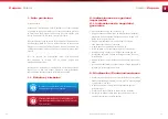
Unfolding
•
Position the rollator in the travel direction.
•
Release the locking brakes (see sec. 4.5.).
•
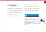
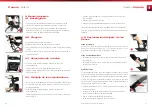
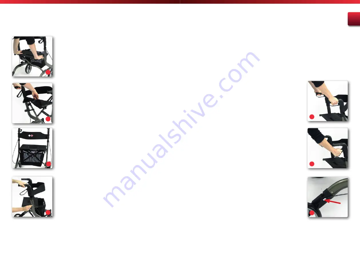
Press the frame tubes of the seat downward to unfold the rollator
(Fig. 3). Make sure the tubes are aligned properly and snap into
place.
4.2.
Folding
•
Activate the locking brakes.
•
Hold the rollator firmly with one hand on the handle. With your
other hand pull the grip on the seat upward (Fig. 4).
•
When doing so you must overcome the resistance of the locking
device.
4.3.
Attaching the bag
•
The rollator is unfolded. Activate the locking brakes.
•
Position yourself against the travel direction in front of the rollator.
•
The bag can be inserted from above in the guide rails on the left
and right on the rollator (Fig. 5).
4.4.
Adjusting the push handles
•
Now adjust the push handles so that they are located at the height
of your wrists. Select the nearest hole in the push tube.
•
The rollator is unfolded. Activate the locking brakes.
•
Hold the push handle firmly with one hand. With the other hand,
activate the locking device (Fig. 6).
•
Move the push handle to the desired height until it latches audibly.
•
Repeat this procedure on the other side.
•
Check to make sure that both the push handles are at the same
height.
The push handles can also be removed with this procedure. To do so,
press the pushbutton and pull the push handle up and out.
4.5. Adjusting / activating the
brakes
Service brake
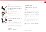
To activate the service brake, pull both handbrake levers upward on
the push handles upward (Fig. 7). Service and locking brake act on the
fixed wheels.
Locking brake
•
Press down on both brake levers to activate the locking device
(Fig. 8).
•
To release the locking brake pull both brake levers back into middle
position.
Adjusting the brakes
We recommend adjusting the brakes together with your specialist
dealer. If you have the necessary technical knowledge, you can do this
yourself as well.
The brake is set properly, if the brake pins do not touch the wheel and
the locking brake can be activated easily.
•
Loosen the locknut (Fig. 11, arrow) so the adjustment nut can turn.
•
Now turn the wide adjustment nut further inwards or outwards to
increase or decrease the braking effect.
•
Retighten the locknut.
•
Repeat the procedure on the other brake if necessary.
3
4
5
8
6
7
9


