'
DO NOT ATIEMPT TO DRILL THROUGH AN ALL-PORCELAIN SINK. If you have an all-
porcelain sink, mount the faucet in pre-drilled sprayer hole or drill through countertop next to
sink..
When drilling through a countertop make sure the area below the drilled area is free of wiring and piping.
Make certain there is ample room to make the proper connections to the bottom of the faucet.
Do not
drill
through a countertop that is more than 25mm (1-inch) thick.
Do not attempt to drill through a tiled, marble, granite or similar countertop. Consult a plumber or
the countertop manufacturer for advice or assistance.
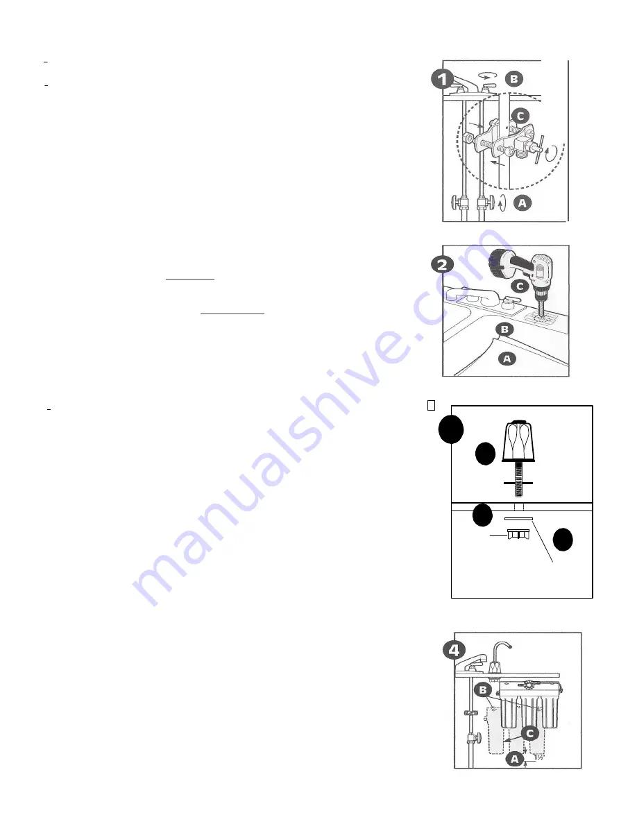
(A) Line bottom of sink with newspaper to prevent metal shavings, parts, or tools from falling down drain.
(B) Place masking tape over the area to be drilled to prevent scratches if drill bit slips.
(C) Mark hole with center punch. Use a 6mm (l/4-inch) drill bit for a pilot hole, then, using a 13mm
(3/4- inch) drill bit or hole saw, drill a hole completely through the sink. Smooth rough edges with a
file.
3. Mounting the Faucet
(A) Remove wing nut
(C)
and metal washer
(B)
from the threaded shaft of the faucet. Leave
the black rubber washer
(A)
on the threaded shaft.
(B) Slide the threaded shaft of the faucet into drilled hole.
(C) From under the sink, slide the metal washer on and thread on the wing nut. Tighten wing nut by hand
until tight. I t may be necessary to have a second person hold the faucet while tightening the
wing
nut.
NOTE:
Do not over tighten the wing nut. Hand tighten only. Do not use pli iers or wrench to tighten.
4. Mounting the System
(A) Center system between water supply adapter and drinking water faucet.
NOTE:
Allow 38 mm (1.5 inches) clearance below system to enable filter cartridge changes.
(B)
Install
mounting screws at least 380 mm (15-inches) from cabinet floor and 235 mm (9 1/4 inches)
apart
.
Leave enough space [approximately 13 mm (l/2-inch)] between the head of the screw and the
wall to slip system onto screws.
(C) Place system over screws on wall and slide sideways. Tighten screws
.
Caution:
Make certain system is firmly attached to wall to prevent it from falling and possibly being
damaged.
5. Connecting the Faucet (diagrams on page 3)
Caution:
Do not over-tighten compression nut. Use caution not to bend or crimp tubes when securing.
(A) Locate compression nuts in installation kit and faucet package.
(8) Attach compression nuts to faucet stem and Effective Life Indicator (ELI) and hand
tighten.
Then
loosen compression nut one full turn.
NOTE:
If the compression nut should come apart, reference diagram 5A for correct reassembly.
6. Attaching Tube
(A) Attach tube to
compression
nut on faucet stem by inserting tube into the compress on nut opening.
Gently push the tubing until it comes to a stop.
Caution:
Tube must be fully inserted in the compress on fitting base to the tube stop on the faucet stem
and on the outlet stem of the ELI.
(B) Turn the nut hand tight.
(C) Wrench tighten the nut 1
½
to 2 turns.
NOTE:
All nuts must be retightened
when
the system reaches projected operating temperature.
NOTE:
A squeaking
sound
when tightening the nut is normal. If fittings are removed, Teflon® tape
must be used for pipe threaded connections.
NOTE:
Compression nut should come preassembled with ferrules inside.
’ F’
nut should come apart, see
figure 5A for proper reassembly.
(D) Determine the length of tubing needed from the faucet to the ELI and cut the tubing. A slight sag in
the lines will allow for some ease in installation. Insert the tubing into the compression nut on the ELI.
Repeat steps 68 and 6C.
7. Connecting the Saddle Valve
A) Determine the length of plastic tubing needed to connect the inlet (left) side of the filter with the
saddle valve. Be sure to allow enough tubing to prevent
kinking
and cut the tubing squarely. Slide
brass compression nut onto tubing, followed by plastic ferrule. The long, tapered end of the ferrule
should face towards the end of the tubing. Place insert into end of tubing.
(B) Insert tubing into saddle valve and hand-tighten compression nut. Using a wrench tighten nut 1 to 1
½
turns.
3
Rubber
Washer
Wing nut
(Page 2)
'
'
•
•
••
'
'
Me
tal
I


