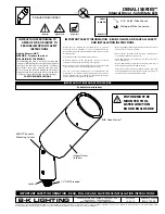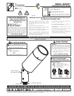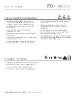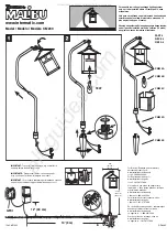
Wiring Diagram
COM
GROUND
LINE
COM
GROUND
LINE
HydroLock Plate
RELEASE DATE
6-28-13
REFERENCE
NUMBER
INS001129
40429 Brickyard Drive • Madera, CA 93636 • USA
559.438.5800 • FAX 559.438.5900
www.bklighting.com • info@bklighting.com
B-K LIGHTING
Fixture Installation
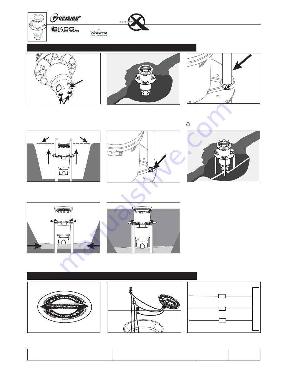
1. Remove temporary cover.
2. Make connections using silicone filled wire
nuts (provided) to leads on the bottom of
Patented Hydro-Lock™Barrier Plate Assembly.
See wiring diagram.
HP2
powered by
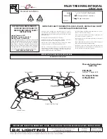
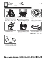
1. Connect branch conduit connectors (By Others)
to the junction box using either the threaded
conduit entries on the bottom of the junction
box or through holes drilled into the sides of the
junction box.
2. Place housing in hole. Align junction box in the
path of the conduit trench.
3. Insert (4) pieces of ½” EMT/Conduit longer than
the height of the hole through the Patented
Stability Flange™. Hammer substrate into
ground until housing is secure.
Leave sufficient clearance to elevate housing
to finished grade.
Flush with finished grade
4. Raise the top of the housing flush to finished
grade using EMT/Conduit for support. Use a
level to aid in housing installation.
If housing
comes with a concrete pour collar (CPC) raise
housing flush to finished grade.
5. When housing is level, tighten screws on
Patented Stability Flange™ to secure housing to
EMT/Conduit. Remove excess EMT as needed.
6. Connect the conduit to the conduit connectors.
7. Per DIG-IT Guide, backfill the gap between the
bottom of housing and bottom of hole with
sand for drainage.
8. Fill and tamp soil to the appropriate height
leaving room for sod, pavers, concrete, etc. to
be level with the top of the temporary cover.
Housing Installation for HP
2
Side Flats