Basic Measurements
31
T2AL 250V
SENSE
Ω
4W
V
Ω
LO
HI
!
10A
CATⅡ(300V)
CATⅠ(1000V)
350V
MAX
1000V
MAX
12A
MAX
mA
12A
INPUT
Diode
▲
▲
▲
▲
DC V
AC V
2W
Fr eq
Aut o
Tr i
g
MX+B
Shi f t
Cont
Rel
¦ ¸
Period
dB/m
Fast
Menu
Recall
Med
Slow
Hold
CHOICES
LEVEL
ENTER
ESC
LOCAL
%
I
DC
I
AC
4W
Ω
FAST
MED
SLOW
ADRS
RMT
HOLD TRIG
*
MEM
AUTO
REL
FILT MATH
SHIFT
4W
ERR
POWER
R
5
5492B
1 2
/
Digit Multimeter
T2AL 250V
SENSE
Ω
4W
V
Ω
LO
HI
!
10A
CATⅡ(300V)
CATⅠ(1000V)
350V
MAX
1000V
MAX
12A
MAX
mA
12A
INPUT
Zener
diode
▲
▲
▲
▲
DC V
AC V
2W
Fr eq
Aut o
Tr i
g
MX+B
Shi f t
Cont
Rel
¦ ¸
Period
dB/m
Fast
Menu
Recall
Med
Slow
Hold
CHOICES
LEVEL
ENTER
ESC
LOCAL
%
I
DC
I
AC
4W
Ω
FAST
MED
SLOW
ADRS
RMT
HOLD TRIG
*
MEM
AUTO
REL
FILT MATH
SHIFT
4W
ERR
POWER
R
5
5492B
1 2
/
Digit Multimeter
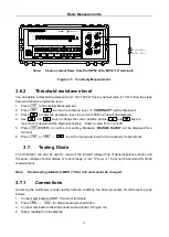
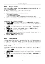
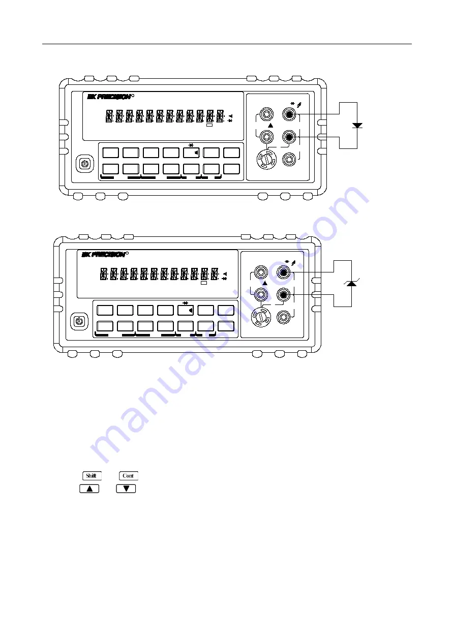
Note:
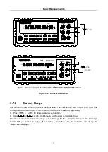
Source current flows from the INPUT HI to INPUT LO terminals
Figure 3-6
Diode Measurement
3.7.2 Current Range
You can set the test current range from the front panel. The choices are 1 mA, 100
μ
A, and 10
μ
A. The
factory default current range is 1 mA. To set the test current, follow the steps below:
1. Press
→
for diode measurement function
2. Using and keys to scroll through the three test current selections.
The diode test function measures voltage on the 3V range for the 1 mA test current and the 10 V range
for the 100
μ
A and 10
μ
A ranges. If a reading is more than 10V, the multimeter will display the
“
OVR.FLW
” message.


