Installation Instructions
JAMISON DOOR COMPANY
18
H4494002 REV B
9.
CABLE CONNECTIONS
•
Locate the light curtain communication cable near the counterweight pulley area.
•
Connect the light curtain cable to the corresponding connector on the motor column assembly.
•
Locate safety switch wire (2-conductors) near the pulley area. Route the safety switch wire to the
control panel make connections per wiring diagram.
•
Mount control panel to a
wall approximately 1400 mm (55”) off the ground and 915 mm (36”) from
the side column. All connections on the control panel must be pointing down.
•
Verify the manual brake handle is in the horizontal position before programming the limits of the
door panel.
•
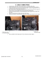
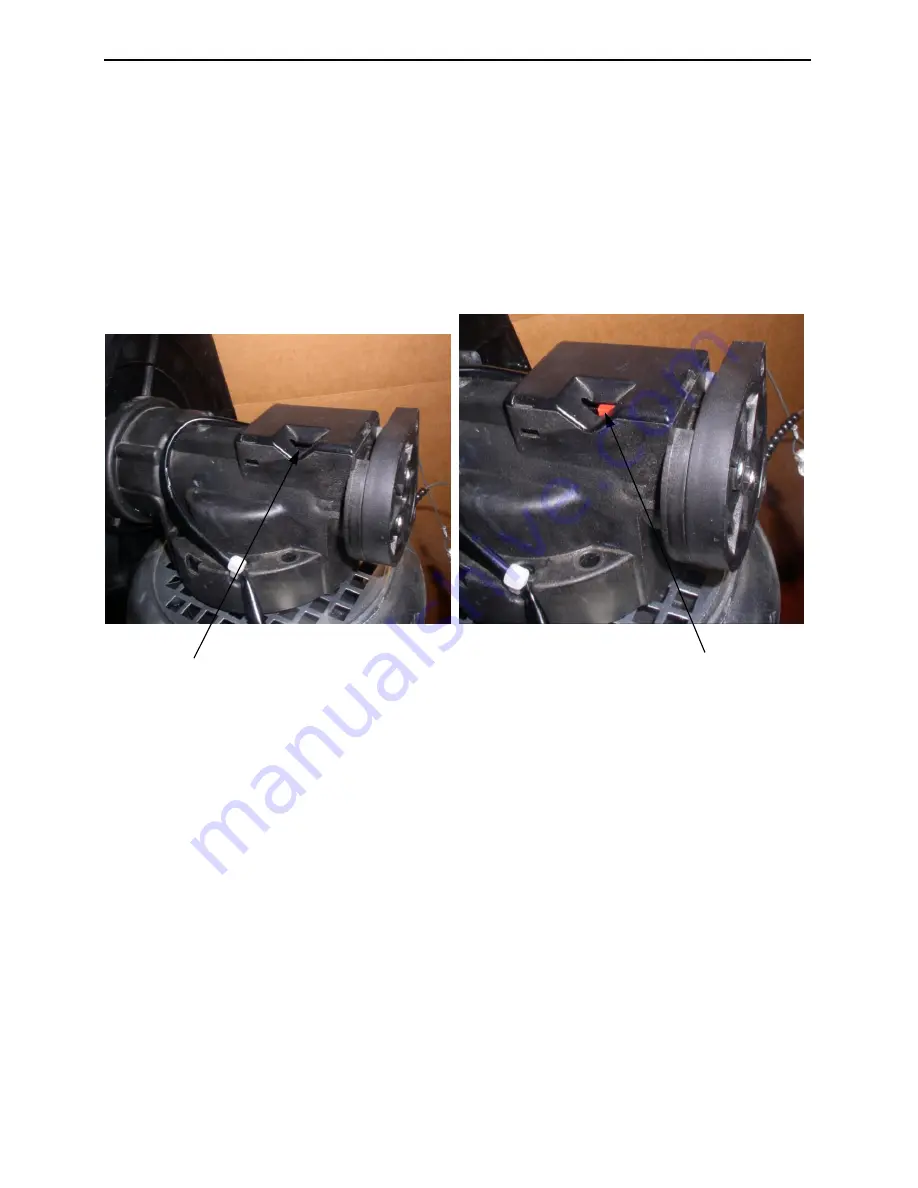
Install chain-fall activation and deactivation ropes and handles.
•
Verify the chain-fall is in the free-wheeling mode before programming the limits of the door panel.
•
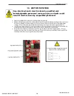
Have a qualified electrician apply power to the control panel per wiring diagram.
Freewheeling mode
(no indicator showing)
Active mode
(Indicator showing)
Summary of Contents for ThermicRoll
Page 2: ...Installation Instructions JAMISON DOOR COMPANY 2 H4494002 REV B...
Page 14: ...Installation Instructions JAMISON DOOR COMPANY 14 H4494002 REV B Pin Set Screw Pin Set Screw...
Page 27: ...Installation Instructions JAMISON DOOR COMPANY 27 H4494002 REV B 17 RADIO CONTROL RECEIVER...
Page 38: ...Installation Instructions JAMISON DOOR COMPANY 38 H4494002 REV B Notes...


