background image

18

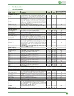
Viewing of screen

Description

U/M

Field

Factory default setting

Round 25 Round 50

TEST PAGE
Resistance Start-up / Shut-down Ignition resistance.

ON/OFF

OFF

Cochlea Shut-down

Internal cochlea.

ON/OFF

OFF

Tank shut-down

External cochlea.

ON/OFF

OFF

Internal Fan

Burner fan.

rpm

0 ÷ 300

0

External Fan.

Cochlea fan.

rpm

0 ÷ 300

0

Air Start-up / Shut-down

Activates 24V electrovalve power supply for the compressed air kit.

ON/OFF

OFF

Alarm Start-up / Shut-down

Activates the 230V output.

ON/OFF

OFF

NOTA

This checks that the main components of the burner are working correctly.
REMOTE CONTROL

Module

Must be activated to connect the GSM module to  connector 6 on 

the burner.

YES / NO

NO

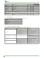
3.8 

Alarm messages

In the event of a fault or malfunction, the following signs appear on the screen:

Description
Failed ignition
Blackout alarm
Faulty water probe alarm
Fuel finished alarm
TS overheating
Fuel finished

3.9 

Problems - Possible causes - Solutions

In the table below are reported the most common problems with their possible solutions.

Problem

Possible cause

Solution

Failed ignition

Empty pellet container

Fill the container

Disconnected or broken external cochlea cable

Reconnect the cable or find the break

Ignition resistance broken

Check the resistance and/or substitute it

Combuston grill is blocked

Pull out the grill and clean it

Internal cochlea blocked

Check the internal cochlea and remove any 

blockages

Power supply absent

Electrical supply to burner not present

Check the mains supply
Check that the electrical cables are connected 

correctly

Check that the general switches and the switches 

on the burner are in the correct position

Water probe

The probe is incorrectly positioned or connected Check its position and connections

Probe faulty

Replace the probe

Fuel finished

Pellet container empty

Fill the container

Disconnected or broken  cochlea cable

Re-establish the connection

Cochlea motor not working

Check the motor

Summary of Contents for B-Home Round 25

Page 1: ...2016 R2 Code INSTRUCTIONS FOR USE INSTALLATION AND MAINTENANCE B Home Round 25 B Essential Round 50 Before installing and using the burner read this manual carefully and keep it close to the burner PE...

Page 2: ...rom electricity so they require special attention and proper preparation d IT IS FORBIDDEN To indication actions which MUST NOT be taken 1 General information 3 1 1 General warnings 3 1 2 Restrictions...

Page 3: ...ly Carry out the operating tests on the appliance and inform the supplier of the product of any anomalies or run ning defects found 1 2 Restrictions d IT IS FORBIDDEN Do not use the appliance in areas...

Page 4: ...connection 10 External cochlea motor connection 11 Manual pellet loading button 12 Fuse 3 15A delayed 13 Main switch 14 Fuse 4A 15 Power socket 230 volts 16 External cochlea fan power socket 17 Connec...

Page 5: ...and the whole system are managed by a control panel with a microprocessor fitted onto the device which as well as managing all the functions also permits the programming of time bands this is useful...

Page 6: ...er EBT0001 P01 280 750 650 1252 70 Pellet container EBT0002 P00 300 800 800 1300 57 1 9 Technical data DESCRIPTION U M B Home Round 25 B Essential Round 50 Burner power kW 12 34 12 50 Power supply V H...

Page 7: ...0Hz M1 M2 24Vdc N F F F F SA ARC TE FR PM1 VPC Main combustion valve VCE External cochlea fan RS Resistance PM1 External cochlea button TE External thermostat SA Water probe FR Photoresistance M1 Exte...

Page 8: ...orage heater if one is installed While the burner is running the external and internal cochleas also work according to the programmed ON and OFF times Once the programmed temperature has been reached...

Page 9: ...onds Ignition shut down of burner Pressure SHORT 1 second Temperature modification Pressure LONG 2 seconds Access to Installer s Menu To gain access it is necessary to know the pass word NB to exit fr...

Page 10: ...emperature 10 90 C To enter burner power levels 1 2 3 4 5 To enter LANGUAGE To enter TIME HOUR FORMAT DATE TEMPERATURE BRIGHTNESS ENABLETIMER WEEKLYTIMER TYPE OF FUEL INFORMATION To enter User Paramet...

Page 11: ...of any non conform ities or complaints the organisation that sold the appliance should be contacted 2 1 2 Contents of the package Burner Burner O ring Socket pipe Flexible hose Seal and burner suppor...

Page 12: ...pass through it If this is not the case adapt it to the diameter make four threaded holes 3 M8 for fixing the burner support flange position the seal 4 supplied with the burner between the flange 5 an...

Page 13: ...R Any applications which are different from the one specified in the manual can cause fire Non insulated exhaust ducts are a potential source of danger It is possible to install a flue valve which con...

Page 14: ...m the burner open the boiler door and check that on the combustion chamber grill THERE IS NO unburnt material If this is not the case it is necessary to modify the settings on the basis of the specifi...

Page 15: ...ming of the user parameters can be done following the flow diagram above after connecting the burner to the mains To enter LANGUAGE To confirm selection To select EN IT ES FR DE Main display To confir...

Page 16: ...o TYPE OF FUEL o To select the type of fuel used A B C D To view type of fuel used o To select the desired level INFORMATION To enter burner power levels 1 2 3 4 5 o To select the desired temperature...

Page 17: ...rts up again sec 0 600 60 Flame stabilisation m Time deemed necessary for stabilisation of the flame after which the burner is enabled to start up min 0 20 1 POWER Cleaning Type Type of combustion bei...

Page 18: ...overheating Fuel finished 3 9 Problems Possible causes Solutions In the table below are reported the most common problems with their possible solutions Problem Possible cause Solution Failed ignition...

Page 19: ...ce refers to the whole plant in which the burner is installed If non certified pellets are used the indications below are rendered null and void since the characteristics of the fuel are not known In...

Page 20: ...ould be used l WARNING The manufacturer Elmec Group S r l DOES NOT ACCEPT RESPONSIBILITY for any damage to people animals or things caused by the use of components that are not original Any modificati...

Page 21: ...21...

Page 22: ...22...

Page 23: ...23...

Page 24: ...ELMEC GROUP S R L Loc Ca d Oro 36020 Asigliano Veneto VI ITALY Tel 39 0444 772023 Fax 39 0444 773129 Mail info b max com Web www b max com...

Reviews: