background image

www.btechavmounts.com

Installation Safety Notes.....................................................................................................................2
BT5890-010 Installation Instructions.......................................................................................................4
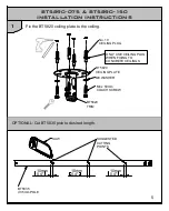
BT5890-075 & BT5890-150 Installation Instructions...............................................................................5
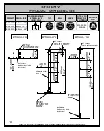
Product Dimensions..........................................................................................................................10
B-Tech Contact Details.....................................................................................................................12

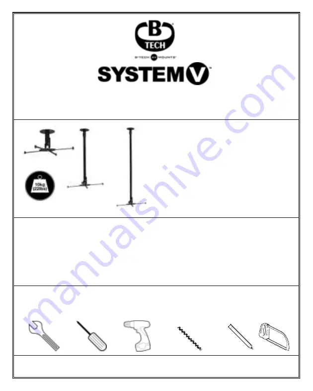
The System V™ range is available in
package or component form.

This installation guide demonstrates
how to install and use the System V™
projector mounting range from
B-Tech.

REGISTERED DESIGN

Flathead

screwdriver

Drill

Pencil

10mm (7/16") masonry bit

or 6mm (1/4") wood bit

13mm (1/2") spanner

or socket

Saw

(Optional)

BT5890-010
BT5890-075
BT5890-150

Summary of Contents for SYSTEM V Series

Page 1: ...Tech Contact Details 12 The System V range is available in package or component form This installation guide demonstrates how to install and use the System V projector mounting range from B Tech REGI...

Page 2: ...falling If you install this product on drywall it must be securely fixed to a wooden stud concrete block or other permanent structure behind the drywall board Installing on drywall boards alone will n...

Page 3: ...ns la limite du poids maximum indiqu IT B Tech International Ltd consiglia di affidare l installazione di questo prodotto a un installatore specializzato o ad altra persona adeguatamente qualificata B...

Page 4: ...iling plate to the ceiling M8 x 55mm SCREW 6mm 0 2 4 BT5820 CEILING PLATE IMPORTANT GO TO STEP 3 ON PAGE 7 ONLY USE CEILING PLUG WHEN FIXING TO CONCRETE CEILINGS No 10 CEILING PLUG BT5820 CEILING PLAT...

Page 5: ...HER M8 x 50mm COACH SCREW BT5820 TRIM BT5820 CEILING PLATE No 10 CEILING PLUG ONLY USE CEILING PLUG WHEN FIXING TO CONCRETE CEILINGS 5 10mm 0 4 10mm 0 4 10mm 0 4 SUGGESTED CUTTING POINTS SAW BT5835 35...

Page 6: ...T5820 ceiling mount BT5835 35mm POLE BT5820 CEILING PLATE M8 x 50mm SCREW M5 x 10mm GRUB SCREW i Fix one M8 x 15mm screw into the BT5835 pole as shown leaving 6mm of thread showing 6mm 0 2 BT5835 35mm...

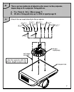
Page 7: ...atterns up to 493mm apart page 8 Attach the carousel directly to the projector Use the spacers with the 25mm length screws only M2 5 x 12mm SCREW M2 5 x 25mm SCREW M3 x 25mm SCREW M3 x 12mm SCREW M4 x...

Page 8: ...MOUNTING SCREW M6 WASHER PROJECTOR MOUNTING HOLE M2 5 x 12mm SCREW M2 5 x 25mm SCREW M3 x 25mm SCREW M3 x 12mm SCREW M4 x 12mm SCREW M4 x 25mm SCREW M5 x 25mm SCREW M6 x 25mm SCREW M6 x 12mm SCREW M5...

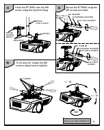
Page 9: ...rew using the keyhole fixing Secure the BT5880 using the M8 screws provided INSTALLATION COMPLETE BT5835 35mm POLE BT5880 M8 WASHER M8 SPRING WASHER M8 x 15mm SCREW M8 x 15mm SCREW M8 SCREW 15 360 15...

Page 10: ...BT5820 CEILING MOUNT BT5820 CEILING MOUNT BT5880 PROJECTOR MOUNT BT5880 PROJECTOR MOUNT BT5880 PROJECTOR MOUNT BT5890 010 BT5890 075 BT5890 150 PRODUCT CEILING DROP MAXIMUM DISTANCE BETWEEN ANY 2 FIX...

Page 11: ...m m 0 9 8 5m m 0 3 42mm 1 7 110mm 4 3 BT5820 CEILING PLATE 493mm 19 4 MAX 493mm 19 4 MAX 143 5mm 5 6 143 5mm 5 6 338mm 13 3 338mm 13 3 100mm 3 9 100mm 3 9 BT5880 INTERFACE 263 5mm 10 4 263 5mm 10 4 F...

Page 12: ...ct names are trademarks of their respective owners Photographs are for illustrative purposes only E OE SINGAPORE Ruby Industrial Complex Singapore 347740 Email info btechavmounts com sg NORTH AMERICA...

Reviews: