4
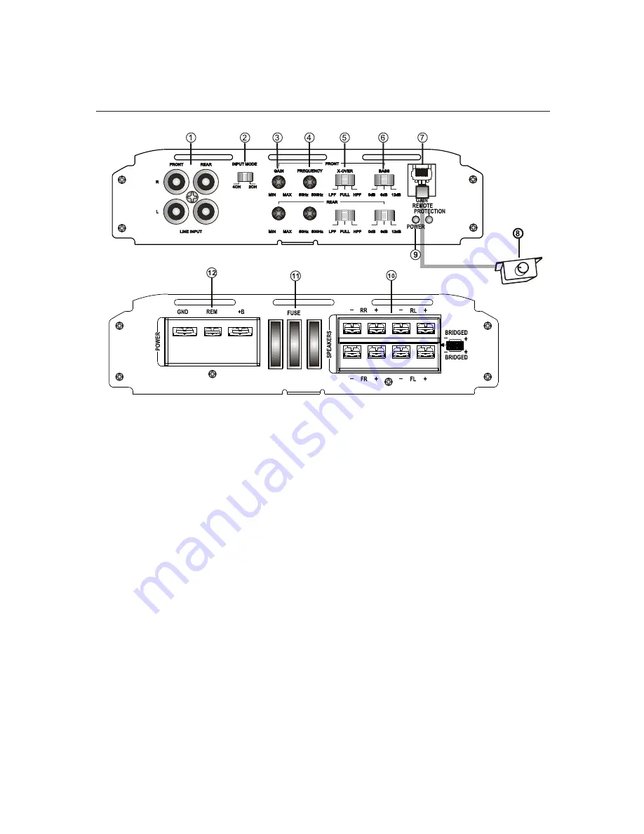
1. Low Level INPUT
RCA connector low level input connected to the speakers of the main unit.
2. High Level INPUT
Input connector plug connected to high-level speakers from the main unit.
NOTE: Do not connect cables high level input if you use the low level RCA input
3. Gain Adjustment (GAIN)
Adjust to obtain the desired volume without distortion.
4. X-OVER: Cutoff Frequency Selector
Selector HPF (High Pass Filter) / LPF (Low Pass Filter) / FULL.
5. Cutoff frequency control X-OVER (50Hz-500Hz)
Frequency selector for high pass and low pass.
6. Bass Boost (Bass Boost)
Selectable 0dB / +6 dB / +12 dB
7. LED indicator
GREEN LED: Indicates normal amplifier operation
RED LED: Indicates the protection mode
8. Output for Remote Controller
Turn the gain (GAIN) to the maximum before using the remote control.
DESCRIPTION OF FUNCTIONS
9. Remote Control
Gain adjustment from 0.2 V to +6 V
FEATURES AND DESCRIPTIONS
Summary of Contents for ELP 36.4
Page 6: ...ELECTRICAL DIAGRAM a Configuration Diagram for 4 Channel Stereo 6...
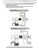
Page 7: ...ELECTRICAL DIAGRAM a Mode Setup diagram Bridge Bridge 7...
Page 10: ...www b52audio com NOTES...
Page 16: ...DIAGRAMA ELECTRICO a Diagrama de Configuraci n para 4 Canales Est reo 16...
Page 17: ...DIAGRAMA ELECTRICO b Diagrama de Configuraci n en Modo Puente Bridge 17...
Page 20: ...www b52audio com NOTAS...
Page 26: ...DIAGRAMA ELETRICO a Diagrama de Configura o para 4 Canais Est reo 26...
Page 27: ...DIAGRAMA ELETRICO b Diagrama de Configura o no Modo Ponte Bridge 27...
Page 30: ...www b52audio com NOTAS...
Page 31: ...MOBILE ENT E RTA INM E NT SY ST E M www b52audio com...


