INSTALLATION
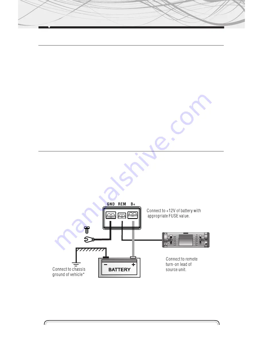
Connect the cable (+) battery to the positive terminal of the amplifier (B +) and ground wire
(GND) of the amplifier to the vehicle chassis. The cable terminal (REM) the terminal cable must
be connected to the stereo remote control
The black wire is the ground wire. When installing this unit, always connect the ground wire first.
Check the ground wire is properly connected to the chassis of the vehicle
Note
To prevent the ground wire (GND) to loosen or fall off the vehicle chassis, you can install a screw
and nut self-braking.
5
10. Fuse Holder
Only replace fuses with same rating fuses
11. Speaker connection terminals
12. (GND) Ground Wire Terminal
A Node connection to the vehicle chassis.
(REM) Remote Control Terminal at Stereo
The terminal (REM) is connected by remote cable to the main unit.
The voltage must be between 10 and 15 VDC
(B +) Terminal of Cable Positive
Power connection terminal. Connect to the anode of the car battery.
FEATURES AND DESCRIPTIONS
Summary of Contents for ELP 36.4
Page 6: ...ELECTRICAL DIAGRAM a Configuration Diagram for 4 Channel Stereo 6...
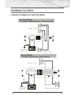
Page 7: ...ELECTRICAL DIAGRAM a Mode Setup diagram Bridge Bridge 7...
Page 10: ...www b52audio com NOTES...
Page 16: ...DIAGRAMA ELECTRICO a Diagrama de Configuraci n para 4 Canales Est reo 16...
Page 17: ...DIAGRAMA ELECTRICO b Diagrama de Configuraci n en Modo Puente Bridge 17...
Page 20: ...www b52audio com NOTAS...
Page 26: ...DIAGRAMA ELETRICO a Diagrama de Configura o para 4 Canais Est reo 26...
Page 27: ...DIAGRAMA ELETRICO b Diagrama de Configura o no Modo Ponte Bridge 27...
Page 30: ...www b52audio com NOTAS...
Page 31: ...MOBILE ENT E RTA INM E NT SY ST E M www b52audio com...


