Troubleshooting
Before installing your amplifier, read the notes you see below and follow the procedures. Always
test the speakers and their cables before installing them in the vehicle.
No power
Check if the ground wire (GND) is properly installed.
Check dif the arrival of energy in the terminal (B +).
Check the fuses.
Check if the LED is turning it protection. it it is, turn the amplifier off for a few minutes and then on
again.
Shrill whistle or engine noise in speakers
Disconnect each of the RCA inputs on the amplifier until the hissing disappears. If the hiss disap-
pears, then replace the cables. If by changing cables, whistling doesn´t disappear, check that the
main drive cables are not touching other wires of the vehicle.
The best way to establish the level of the amplifier is putting his gain to the maximum. Try to raise
the signal level on the main unit as much as possible and see if the hiss decreases.
Protection LED is activated when the amplifier is operating
Check for a short-circuit in the line of speakers.
Turn off the amplifier, disconnect all the speakers and turn on the amplifier. If the protection LED
turns on again, then is the amplifier is not working properly.
If the heat sink temperature exceeds 85° C, the power supply is disconnected automatically This
protecting the amplifier against a damage.
The amplifier overheats
Verify that the minimum speaker impedance is correct for the amplifier.
Check if the speaker wires have a short circuit.
Make sure if there is enough ventilation over the amplifier.
The sound is distorted
Verify that the gain control of the main unit is correct.
Check that all crossover frequencies are configured correctly.
Verify that the speaker wires are not touching each other.
Squealing noise in the speakers
The squeak maybe caused by a damaged cable or poor contact on the ground.
TROUBLESHOOTING
8
Summary of Contents for ELP 36.4
Page 6: ...ELECTRICAL DIAGRAM a Configuration Diagram for 4 Channel Stereo 6...
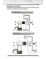
Page 7: ...ELECTRICAL DIAGRAM a Mode Setup diagram Bridge Bridge 7...
Page 10: ...www b52audio com NOTES...
Page 16: ...DIAGRAMA ELECTRICO a Diagrama de Configuraci n para 4 Canales Est reo 16...
Page 17: ...DIAGRAMA ELECTRICO b Diagrama de Configuraci n en Modo Puente Bridge 17...
Page 20: ...www b52audio com NOTAS...
Page 26: ...DIAGRAMA ELETRICO a Diagrama de Configura o para 4 Canais Est reo 26...
Page 27: ...DIAGRAMA ELETRICO b Diagrama de Configura o no Modo Ponte Bridge 27...
Page 30: ...www b52audio com NOTAS...
Page 31: ...MOBILE ENT E RTA INM E NT SY ST E M www b52audio com...


