IS-033
___________________________________________________________________________
_______________________________________________________________________________________
Baader Ísland ehf, Hafnarbraut 25, Kopavogur, Iceland Tel: +354 520 6900 Fax: +354 520 6911
lager@baader.is / www.baader.is
36
Page 36
Adjustment of the trigger
Prior to working on the machine switch the main electrical switch to the
0
position and lock it. Failure to comply may result in serious personal injury or
death.
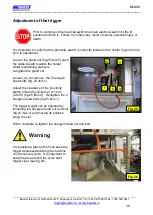
It is important to verify that the proximity switch is correctly located in the holder (fig.23 item 2)
prior to adjustment.
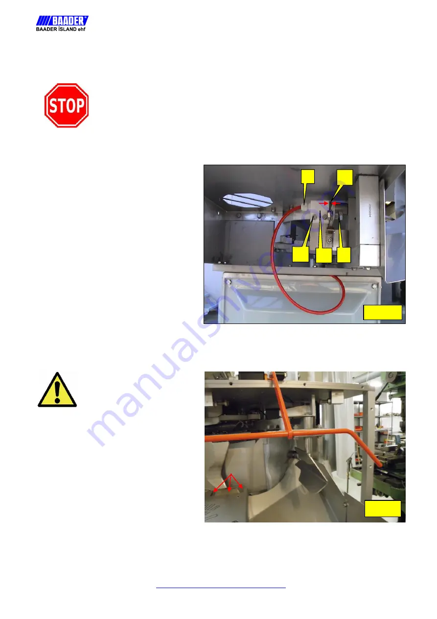
Loosen the gland nut (fig.25 item 5) push
the cable sheath towards the holder,
whilst maintaining pressure
re-tighten the gland nut.
Loosen, do not remove, the 2 hexagon
head bolts (fig. 25 item 1).
Adjust the clearance of the proximity
switch holder (fig.25 item 2) to 1mm
(0.040") (fig.25 item 4). Re-tighten the 2
hexagon head bolts (fig.25 item 1).
The trigger weight can be adjusted by
loosening the hexagon head nut and bolt
(fig.25 item 3) and moving its position
along the slot.
When complete re-tighten the hexagon head nut and bolt.
Warning
It is possible a piece of fish can keep the
trigger depressed allowing the machine
to continuously cycle. It is important to
keep the area around the cycle start
trigger clear (see fig.26).
Fig 26
Fig 25
2
1
3
4
5


