background image

.

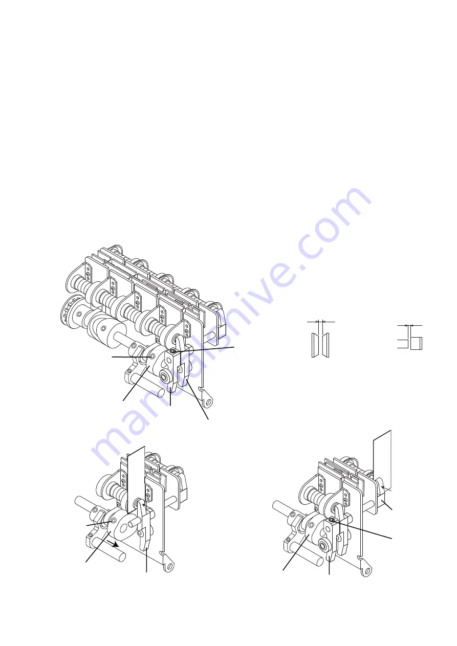
Cam

Cam

Front disk moving 
arm set

Front disk 
pushing arm set

Rear disk moving 
arm set

Rear disk moving 
arm set

16. REPLACEMENT OF ROLLERS OF A.T.D.

1) Loosen the screw (1) and remove Frontdisk moving arm set.
2) Remove Rear disk moving arm set.
3) Loosen the screw (2) and replace Cam.The screw should be placed at the flat of shaft.       
4) Replace Rear disk moving arm set.
5)Turn handwheel and bring the roller of Rear disk moving arm set at the bottom position of Cam. 
    Insert 0.4mm thickness gauge between disk pushing shaft and Rear pushing arm section.
    Push and keep Rear disk pushing arm section at bottom of pre-tenstion position,adjust Cam to
    the roller has just touched on the bottom of Cam. Tighten the Screw (2).
    Remove thickness gauge, make sure the distance of disks is 0.9mm when opened. 
6) Replace Front disk moving arm set.  
7) Turn handwheel and bring the roller of Front disk moving arm set at the bottom position of Cam. 
     Insert 0.4mm thickness gauge between disk pushing shaft and front pushing arm set.
     Push and keep Front disk pushing arm set at bottom of pre-tenstion position,and adjust Cam to
     the roller has just touched on the bottom of Cam.
     Hold Front disk pushing arm set to leftward and Front disk moving arm set to rightward,
    and tighten the Screw (1).
    Remove thickness gauge, make sure the distance of disks is 0.9mm when opened.
    Make sure Front disk pushing arm set does not have a play. 

0.4

0.4

0.9mm

0.4mm

Screw(1)

Screw(2)

Screw(2)

Distance of disks 
when opend

Distance of 
pre-tension

Cam

Front disk moving 
arm set

Screw(1)

Adjustment of Rear disks 

Adjustment of Front disks 

17

Summary of Contents for BL-5180

Page 1: ...Baby Lock BL 101 BL 450 BL4 838D BL 5180 BLE1 BLE1SX BLE1DX BLE1AT BLE3ATW BLE8 BLE8W and BLCS Service Manuals...

Page 2: ...SERVICE MANUAL Model BL 101...

Page 3: ...le a Set needle holder to extreme right position b Adjust the distance of needle holder 2 Adjustment of needle guards and needle guide plate Set needle slightly right down ward in order to make its pe...

Page 4: ...1 3 Adjustment of looper position 3 1 Adjustment of top and bottom position 3 2 Clearance between the looper tip and the needle 3 3 Distance from the eye of needle to the looper tip 2...

Page 5: ...stitch dial at skip position when you adjust the timing 6 Adjustment of the height of cloth lifter Set stitich depth dial at 3 centre 7 Adjustment of cloth presser Make sure both left and right cloth...

Page 6: ......

Page 7: ......

Page 8: ......

Page 9: ......

Page 10: ......

Page 11: ......

Page 12: ......

Page 13: ......

Page 14: ......

Page 15: ......

Page 16: ......

Page 17: ......

Page 18: ......

Page 19: ......

Page 20: ......

Page 21: ......

Page 22: ......

Page 23: ......

Page 24: ......

Page 25: ......

Page 26: ......

Page 27: ......

Page 28: ......

Page 29: ......

Page 30: ......

Page 31: ......

Page 32: ......

Page 33: ......

Page 34: ......

Page 35: ......

Page 36: ......

Page 37: ......

Page 38: ......

Page 39: ......

Page 40: ...SERVICE MANUAL MODEL BLCS Vol 2 0 From To Serial Numbers For U S A For Canada For Europe Australia NZ 100051 100176 100389 100333 100382 100060...

Page 41: ...ooper shaft Distance of upper looper tip from right side of overlock right needle O 2 Distance of lower looper tip from right side of overlock right needle O 2 Distance of chain looper tip from right...

Page 42: ...adjustment 1 9 0 0 1 ELx705CF 90 14 ELx705CF 90 14 ELx705CF 90 14 ELx705CF 90 14 C 3 Needle 2 Needle plate 10 2 0 05 C 3 Needle 0 0 2 3 0 2 0 Chain Needle Chain Needle Needle guard adjustment 0 2 0 3...

Page 43: ...eck disks are open perfectly when presser bar lifter is lifted 4 2 Dropped feed dog adjustment Make sure feed dog height is correct before you adjust following items a Loosen adjusting screw B b Lift...

Page 44: ...4 0 9 0 1 0 3 Height of feed dog 4 Tension release Dropped feed dog adjustment A C B D E...

Page 45: ...Remove bace plate c Remove piston driving arm fixing screw 11 SM3005IK d Remove piston driving arm from piston driving shaft It will be easy to remove the arm from the shaft if you push the shaft to...

Page 46: ...3 5 4 3 9 8 15 12 13 4 17 2 1 6 10 14 11 16 7 6 Threading steel pipe Proper position Unproper position Joint 5 Checking thread steel pipe joint 6 Checking pump...

Page 47: ...ruction Book P 14 15 Are the threads snapped in the head guide See Instruction Book P 15 Are the threads recommended high quality See Instruction Book P 7 7 3 THREAD BREAKS Is the BLCS threaded correc...

Page 48: ...X BLE1AT BLE3ATW BLE8 BLE8W BLCS Vol 6 1 From Serial Numbers 8W K6 104507 ATW K6 148120 AT K6 104551 8W 101484 ATW 101141 AT 705451 DX 715850 8W 101201 8 501001 ATW 101081 AT 705771 DX 715800 8W 10023...

Page 49: ...e Needle System HAx1 130 705H SCHMETZ ORGAN Model Household Sewing Machine Plating Nickel Front Groove Needle System HAx1SP CR ORGAN SCHMETZ Model BLE1SX DX LX AT ATW BL101 Plating Chrome Front Groove...

Page 50: ...wise Raise needle b Height of presser foot Raise the presser foot lifter Loosen screw B and move the presser foot bar to raise or lower You are required to check the clearance between needle and press...

Page 51: ...er looper to the center of left right needle Loosen looper arm screw and adjust lower looper to the correct position Lower looper fixing screw Right Needle Lower looper position 3 5 5 7 m m 0 1 11 75...

Page 52: ...do not touch needles strongly and the distance between upper looper and needles is not big Repeat a to e until you get exact position 4 0 8 0 3 Looper arm screw for adjusting position a Replacement of...

Page 53: ...ockwise Raise feed dog Counter clockwise Lower feed dog Presser foot Pressure 1mm 1mm a FEED DOG HEIGHT ADJUSTMENT a FEED DOG POSITION ADJUSTMENT Screw of Main feed dog Rear Screw of Sub feed dog Fron...

Page 54: ...er Differential feed positining ratchet Screw Stitch length dial Sub feed dog front Main feed dog rear How to adjust a Move differential feed adjusting lever to get same moving length of main and sub...

Page 55: ...Pin Chaining tongue holder pin Chaining tongue holder Chaining tongue holder pin Adjusting chaining tongue Adjusting chaining tongue Screw A B a Move the pin to leftward b Remove chaining tongue hold...

Page 56: ...ce it b Fixing screw temporaly turn the hand pulley and bring the upper knife to the lowest positon c Adjust upper knife to be 1 1 5mm overlapping with cutting face of lower knife d Tighten firmly fix...

Page 57: ...edle O2 Thread No Use Stitch Width M Stitch Length 2 5 Differencial feed N Fabric Cotton broad 1 layer 3 7 0 1mm Fixing screw of Knife holder 5 5 3 0 Fixing screw of Knife holder Fixing screw of knife...

Page 58: ...D You are required to adjust NEEDLE THREAD SENSOR CABLE first Sewing Test with long poli span thread a 1 Needle 3 thread nomal sewing Needle Right Needle O2 Thread Long poli span thread 60 or short po...

Page 59: ...thread end in the threading port 4 Is there at least 40cm of loose thread beyond the threads guide above the threading port 5 Is there a kink or twist in the 40cm of thread to restrict the blow into...

Page 60: ...are in the center of the joint pipe receivers or not By same method as mentioned a check whether end of the joint pipe is in the centerof the pipe receiver or not In case that the end of the joint pip...

Page 61: ...Replace the piston cap to the new one 4 Give a amall amount of grease MOLYKOTE EM 50L around the piston cap and return the piston assembly to cylinder 5 Fit the piston driving shaft to the piston dri...

Page 62: ...A and B and adjust the position of looper thread take up guide 1 and overlock looper threading pipe holder set 2 so that joint pipes 3 may move smothly CHAIN LOOPER Loosen the screw C and D and adjust...

Page 63: ...grees while pushing the lock button and moving the releace lever right and left direction slowly and gently with left hand find out the best position that the end of joint pipes are in the center of l...

Page 64: ...ard and remove lower looper threading pipe downward and rightward 4 In case of replacing Joint pipe with new one remove it with Joint pipe spring very carefully 5 Replace Lower looper threading pipe 6...

Page 65: ...hten the Screw 2 Remove thickness gauge make sure the distance of disks is 0 9mm when opened 6 Replace Front disk moving arm set 7 Turn handwheel and bring the roller of Front disk moving arm set at t...

Page 66: ...t of Lower looper driving cam or Rollers you are required to do next steps 4 Remove the nut 11 of Needle driving rod set 6 and loosen the screw 13 5 Remove Needle driving rod set 6 from Lower looper d...

Page 67: ...ect position See page 2 and 3 2 Adjustment of engage position Loosen 2 screws of Machine engage plate set Turn handwheel and find out the end of joint pipes are in the center of looper joint pipes Tur...

Page 68: ...1 2 3 4 5 6 7 8 9 10 Main shaft For Lower looper driving cam For Knife driving cam For Feed dog driving cam A 8 7 0 2mm 12mm For BLE8 BLE8W BLCS For BLE1SX BLE1 BLE1DX BLE1LX BLE1AT BLE3ATW...

Page 69: ...e BLCS 3 For BLE5 BLE8W For BLE3ATW For BLCS 3 For BLE1SX DX AT Height of feed dog Distance of lower looper tip from center of lower looper shaft Distance of chain looper tip from center of chain loop...

Reviews: