Application of
Disassembly
3 - 6
Main frame and covers
Application o
f
Disassembly
Application of Disassembly
6
Disassembly of Front cover assy
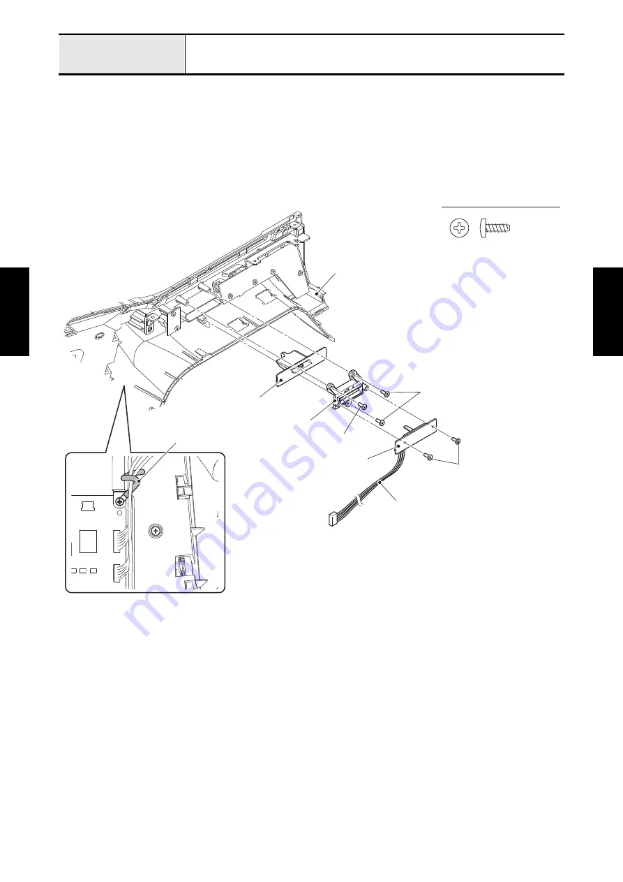
6-1 Removal of VR PCB assy, SV keytop assy, Threader switch PCB assy and Threader button
1. Release the clip to unbind the any lead wire.
2. Disconnect the VR PCB lead wire from the panel PCB assy.
3. Remove the two screws (taptite, bind B M3x8) to remove the VR PCB assy from the SV guide.
4. Remove the three screws (taptite, bind B M3x8) to remove the SV guide and SV keytop assy from the
front cover assy.
Taptite, Bind B M3X8
SV keytop assy
SV guide
Taptite, bind B M3x8
VR PCB assy
Taptite, bind B M3x8
VR PCB lead wire
Clip
Front cover assy
Taptite, bind B M3x8
Summary of Contents for BLDY
Page 2: ......


