Application of
Assembly
3 - 141
Main frame and covers
Application o
f
Assembly
Application of
Assembly
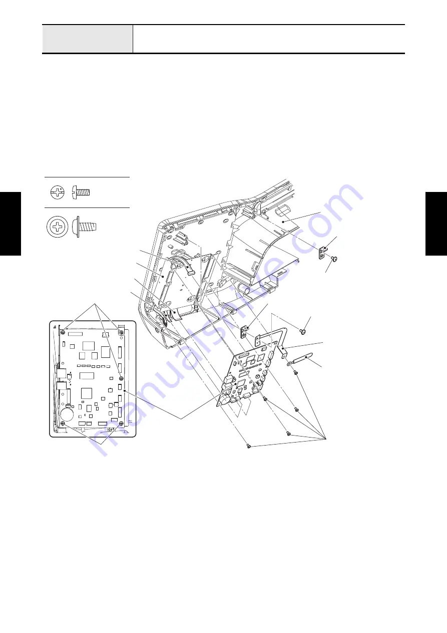
2. Attach the panel PCB assy to the panel board holder with the four screws (screw, bind M3x6).
3. Connect the lead wire assy MFFC to the CN8 on the panel PCB assy. Connect the FFC of touch panel
to the CN10 on the panel PCB assy, and lock it. Connect the flexible flat cable:20706ASFBI to the CN7
on the panel PCB assy, and lock it.
*Key point
• Refer to
.
4. Align the positioning hole of plate E with the boss of front cover assy, and attach the plate E and the
panel board ground plate U to the front cover assy with the screw (taptite, cup B M4x8). Attach the
panel board ground plate U and the clip to the panel board holder with the screw (screw, bind M3x6).
5. Align the positioning hole of plate E with the boss of front cover assy, and attach the plate E to the front
cover assy with the screw (taptite, cup B M4x8).
Taptite, Cup B M4X8
Screw, Bind M3X6
Front cover assy
Plate E
Taptite, cup B M4x8
Panel board ground plate U
Screw, bind
M3x6
Panel PCB assy
Clip
Screw, bind M3x6
Screw, bind M3x6
FFC
Flexible flat cable:20706ASFBI
Taptite, cup B M4x8
Plate E
Lead wire assy MFFC
Panel board holder
Summary of Contents for BLDY
Page 2: ......