Application of
Assembly
3 - 145
Main frame and covers
Application o
f
Assembly
Application of
Assembly
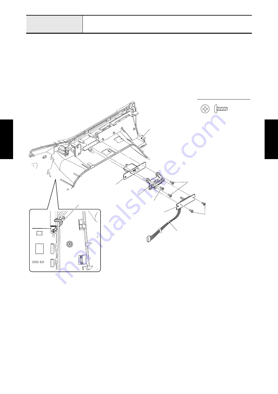
9-8 Attachment of SV keytop assy and VR PCB assy
1. Set the SV keytop assy and SV guide to the front cover assy, and secure them with the two screws
(taptite, bind B M3x8).
2. Insert the SV keytop slider into the positioning hole of SV keytop assy, and attach the VR PCB assy to
the SV guide with the two screws (taptite, bind B M3x8).
3. Connect the connector of VR PCB lead wire to the CN2 on the panel PCB assy, and clip the each lead
wire together.
*Key point
• Refer to
"Wiring of Right side of Front cover assy"
.
Taptite, Bind B M3X8
SV keytop assy
SV guide
Taptite, bind B M3x8
VR PCB assy
Taptite, bind B M3x8
VR PCB lead wire
Clip
Front cover assy
Taptite, bind B M3x8
Summary of Contents for BLDY
Page 2: ......