Application of
Assembly
3 - 181
Feed module
Application o
f
Assembly
Application of
Assembly
3
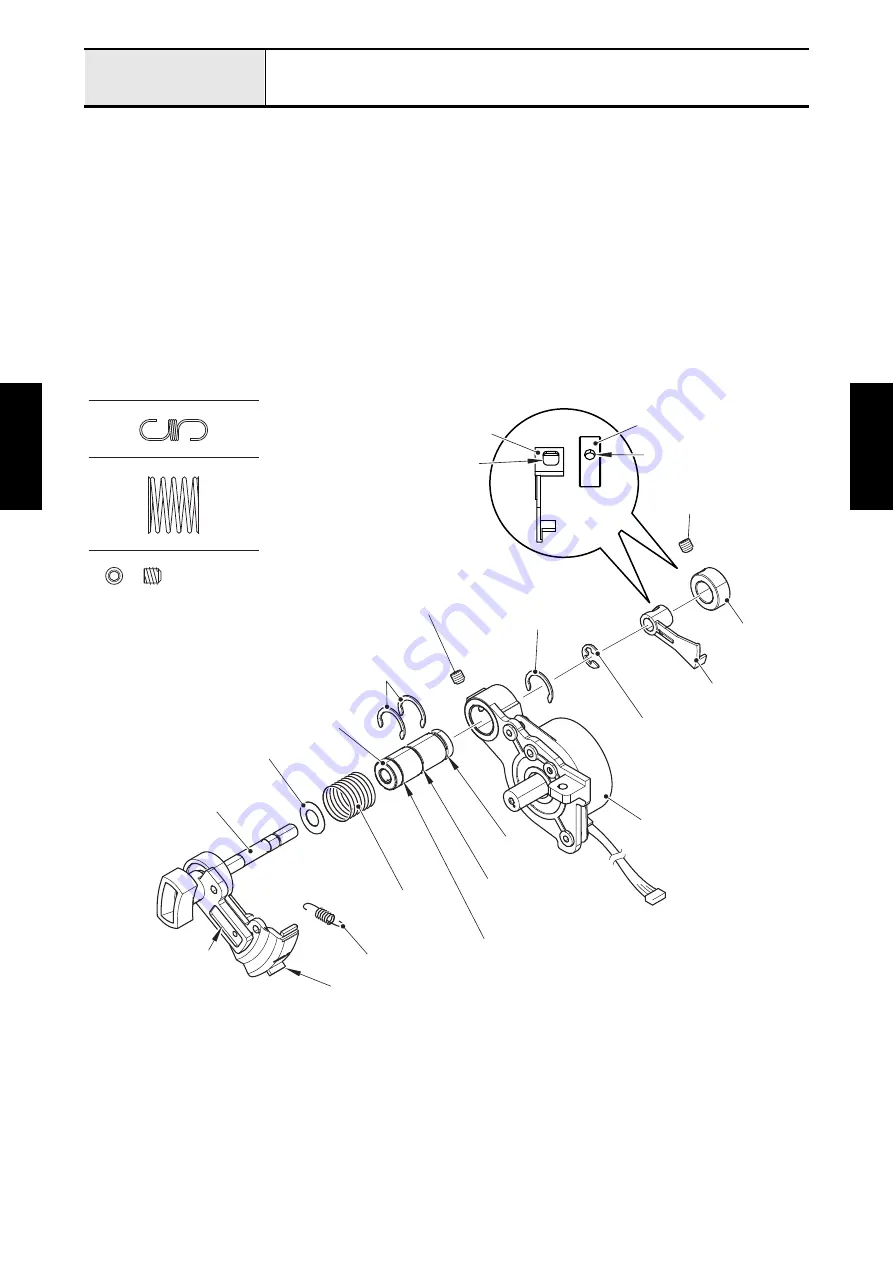
Attachment of Feed adjuster gear assy, F INIT PCB assy and FPM holder assy
1. Attach the two retaining rings 10 to the groove A and B on shaft bushing.
2. Insert the shaft bushing to the FPM holder assy, tighten the screw (set screw, socket (CP) M4x4)
temporarily, and attach the retaining ring 10 to the groove C on shaft bushing.
3. Attach the spring (XC2530) to the feed adjuster and feed gear.
4. Set the washer and spring (XE4082) to the feed adjuster gear assy. Insert the feed adjuster gear assy
to the shaft bushing, and then attach the retaining ring E4 to the shaft of feed adjuster gear assy while
pushing it to the right side.
5. Set the set collar to the F initial shutter, and set them to the shaft of feed adjuster gear assy. Align the
screw hole of set collar with the positioning hole of F initial shutter, and tighten the screw (set screw,
socket (CP) M4x4) temporarily.
*Key point
• Fully tighten the screw after performing
“Alignment of Feed adjuster gear assy and F initial shutter position”
.
SPRING (XE4082)
SPRING (XC2530)
Set Screw, Socket (CP) M4X4
Set collar
Screw hole
Set screw, socket
(CP) M4x4
F initial shutter
Positioning hole
Set collar
Retaining ring E4
FPM holder assy
Retaining ring 10
Retaining rings 10
Feed adjuster gear assy
Washer
Groove C
Shaft bushing
Groove B
Groove A
Spring (XE4082)
Spring (XC2530)
Feed gear
Feed adjuster
Set screw, socket
(CP) M4x4
F initial shutter
Summary of Contents for BLDY
Page 2: ......


