Basic of Assembly
2 - 50
Lower driving mechanism
Basic of Assembly
Basic of Assembly
3
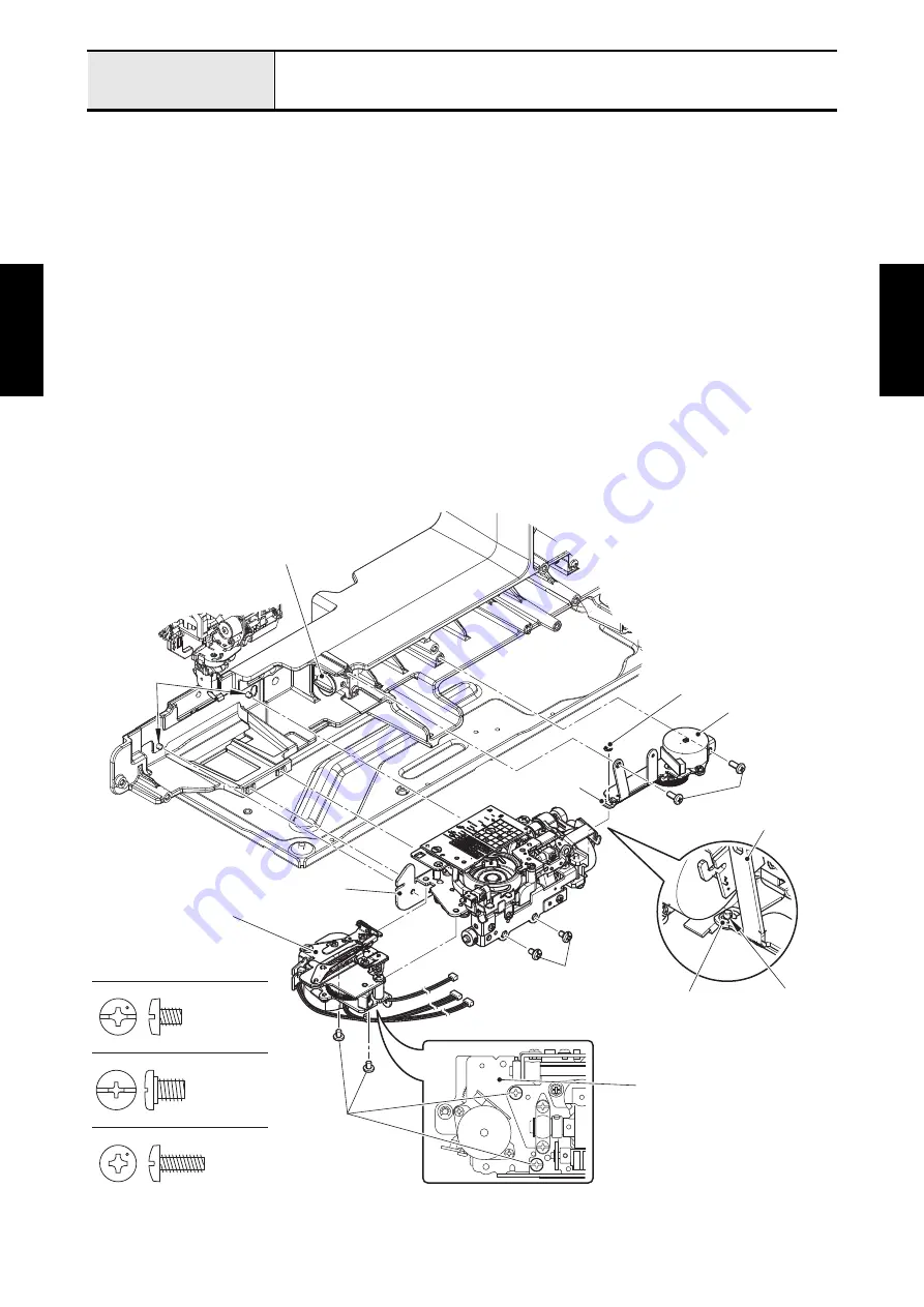
Attachment of Thread cutter module, Feed module and Drop unit assy
1. Align the boss of thread cutter module with the positioning hole of feed module, and attach the thread
cutter module to the feed module with the two screws (screw, bind M4x5).
Refer to 3 - 172 Thread cutter module.
2. Pass the each lead wire of thread cutter module through the securing fixtures. Bind up the each lead
wire to the feed module with the band A.
*Key point
• Refer to
"Wiring of Thread cutter module / Feed module / Side feed assy"
.
3. Align the groove of joint with the disk, align the two positioning holes of feed module with the two pins of
arm bed, and set the feed module to the arm bed with the two screws (screw M4).
Refer to 3 - 177 Feed module.
4. Set the pull link assy of drop unit assy to the shaft of reversal link assy, attach the drop unit assy to the
arm bed with the two screws (taptite, bind S M4x10), and then attach the retaining ring E2.5 to the shaft
of reversal link assy.
5. Bind up the each lead wire with the band B.
*Key point
• Refer to
"Wiring of Thread cutter module / Feed module / Side feed assy"
.
Taptite, Bind S M4X10
Screw, Bind M4X5
Screw M4
Retaining ring E2.5
Thread cutter module
Screw, bind
M4x5
Retaining ring E2.5
Screw M4
Feed module
Taptite, bind S
M4x10
Shaft of reversal
link assy
Drop unit assy
Drop unit assy
Thread cutter module
Pins
Disk
Pull link assy
Summary of Contents for BLDY
Page 2: ......