Basic of Assembly
2 - 64
Main frame and covers
Basic of Assembly
Basic of Assembly
3
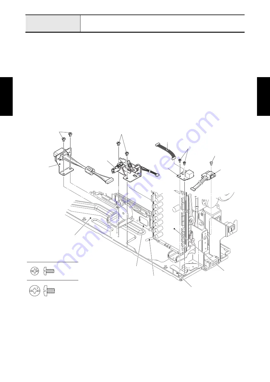
Attachment of UW pen connector PCB assy, Connector holder assy and Knee lifter assembly
1. Attach the extension IF PCB assy L to the sensor connector holder D with the screw (screw, bind
M3x6). Connect the extension IF PCB assy L lead wire to the main PCB assy.
2. Attach the UW pen connector PCB assy to the sensor connector holder D with the two screws (screw,
bind M3x6). Connect the lead wire assy pen connector to the UW pen connector PCB assy and the
main PCB assy.
3. Attach the connector holder assy to the base plate with the two screws (screw, bind M4x6). Connect
the lead wire assy main body to the main PCB assy, bind up the each lead wire to the side feed assy
with the band A, and clip them together.
Refer to 3 - 134 Assembly of Connector holder assy.
4. Attach the knee lifter assembly to the base plate with the two screws (screw, bind M4x6). Bind up the
each lead wire with the band B. Connect the knee lifter assembly lead wire to the main PCB assy.
*Key point
• Refer to
"Wiring of Lower side of Main PCB"
.
Screw, Bind M3X6
Screw, Bind M4X6
Screw, bind M3x6
Screw, bind M4x6
Screw, bind M4x6
Knee lifter assembly
Connector
holder assy
Clip
Main PCB assy
Lead wire assy
pen connector
Sensor connector holder D
Base plate
Side feed assy
Screw, bind M3x6
UW pen
connector
PCB assy
Extension IF
PCB assy L
Summary of Contents for BLDY
Page 2: ......


