4 - 32
Adjustment
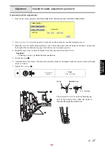
Picker activation adjustment
1. Remove the bobbin case.
2. Enter test mode and press [MAIN BOARD TEST MODE] and then [PICKER MOTOR TEST].
3. Press [MOVE PICKER MOTOR] to release the picker, and then attach the bobbin case with a bobbin inserted to
the rotary hook.
4. Press [MOVE PICKER MOTOR] to turn the picker on.
5. Press [
←
] or [
→
] (OVER PULSE) to adjust the clearance should be 0.45 mm - 1.05 mm between the bobbin
and the picker tip.
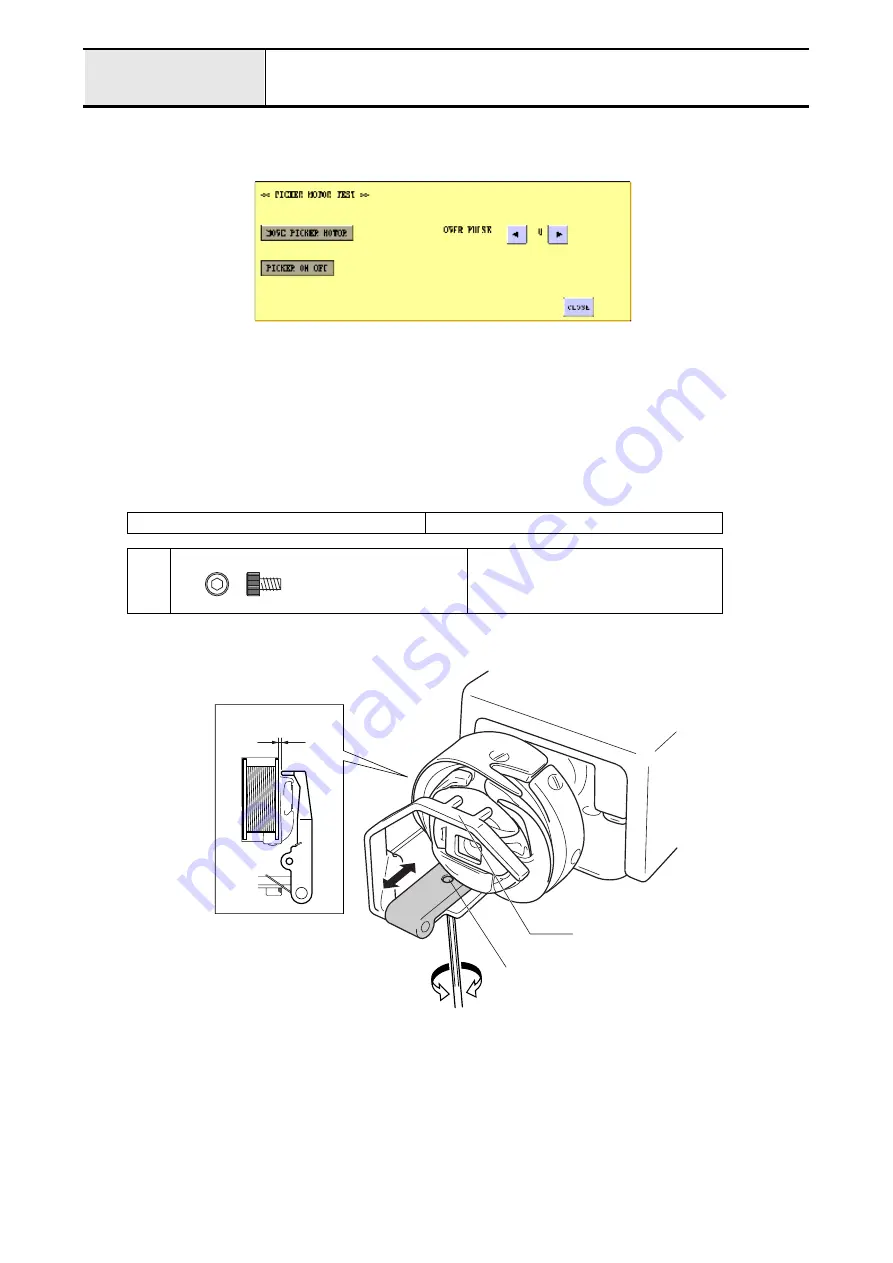
6. If the clearance cannot be adjusted by following the above procedure, move the picker holder attachment screw
1
back and forth to adjust the clearance..
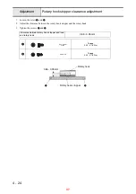
Clearance between bobbin and picker tip
0.95 - 1.05 mm
1
Torque
0.59 - 0.78 N-m
Bolt, Socket
M3X5
Color; Black
0.95 - 1.05mm
Picker
1
44
If a customer is using a bobbin other than a type "L" picker pulse number may need adjusted to
comprehensive. While pushing from the front while the picker is engaged, there should be a slight
amount of play - about 0.5 mm. This will effect the thread cutting.
Summary of Contents for EMP6
Page 1: ...EMP6 BMP8 Technical Training...
Page 16: ...2 55 Disassembly Power unit Main unit 15...
Page 18: ...2 73 Disassembly Operation panel Main unit 17...
Page 44: ......


