background image

WWW.BALTIMOREAIRCOIL.COM

22

heat Transfer Section

Inspect the coil surface. Any corrosion, damage, or obstructions must be corrected.

Fill & Drift Eliminator

The FXV, FXV3, CXVB, and CXVT have PVC fill with integral drift eliminators.

Inspection & Maintenance

•  Inspect and clean the fill with the integral eliminators at least quarterly.
•  The inspection procedure is as follows:


Shut-off the fan and the system pump.


Inspect the fill for obstructions, damage and fouling.

•  Remove any obstructions from the fill.
•  Remove any minor fouling chemically. Contact your local water treatment consultant 

for advice.

•  Major fouling requires cleaning and flushing.

Water Distribution System

The spray water is distributed through a corrosion resistant polyvinyl chloride (PVC) 
distribution system. The drift eliminators are made of PVC, which is impervious to rot, 
decay, rust, or biological attack. Inspect and clean the spray nozzles and heat transfer 
section each month.

The inspection procedure is as follows:

•  Shut-off the fan, but leave the spray pump running.
•  Check to see if the nozzles are producing the spray pattern shown in 

Figure 7

.

•  Clean any nozzles which are clogged. If necessary, the nozzle and rubber grommet 

may be removed for cleaning.

•  Inspect the coil surface. Any corrosion, damage, or obstructions must be corrected.

NOTICE:

 Do not use steam or 

high pressure water to clean PVC 
eliminators or materials other 
than steel.

Figure 7.

 nozzle Spray Pattern

Summary of Contents for FXV-1212C-32Q-M/Q

Page 1: ...OPERATION MAINTENANCE MANUAL FXV and FXV3 Closed Circuit Cooling Tower CXVB and CXVT Evaporative Condenser Model FXV 1212C 32Q M Q ...

Page 2: ...ior Check fan motor for proper rotation Check general condition of the fan Check and unplug fan drain holes hollow blade fans Check fan for uniform pitch Check fan for rotation without obstruction Check and recoat steel shafts with RUST VETO Check basin heater and stand alone BAC heater control panel Test vibration cutout switch DANGER Rotating equipment will cause severe personal injury or death ...

Page 3: ...ements 27 Passivation 27 Biological Control 28 Long Term Care of Stainless Steel 29 System Cleaning PART 4 Bleed Rate PART 5 Cold Weather Operation 32 Inspection and Maintenance 32 Fan Section Icing Protection 33 Basin Water and Internal Piping Freeze Protection 34 Coil Freeze Protection PART 6 Operation Considerations for Accessories 38 Basin Heater 38 Stand Alone BAC Heater Control Panels 40 Vib...

Page 4: ...g water system must wear respiratory protection equipment approved for such use by governmental occupational safety and health authorities CAUTION The operation maintenance and repair of this equipment shall be undertaken only by personnel authorized and qualified to do so All such personnel shall be thoroughly familiar with the equipment the associated system and controls and the procedures set f...

Page 5: ...eneral Maintenance Information Equipment Precautions NOTICE The services required to maintain a piece of evaporative cooling equipment are primarily a function of the quality of the air and water in the locality of the installation AIR The unit should be located such that unusual quantities of industrial smoke chemical fumes salt or heavy dust do not enter the equipment Such airborne impurities en...

Page 6: ...ovable Drift Eliminators BALTIDRIVE Power Train Prime Surface Coil Suction Strainer Spray Riser Pipe Bleed Valve Spray Pump Access Door Spray Pump Motor Make up Valve Axial Fan s Cold Water Basin Recirculating Water Pump Access Door Figure 1 Single Side Air Intake FXV CXVB Coil Connection FXV Fluid In CXVB Refrigerant Out Coil Connection FXV Fluid Out CXV Refrigerant In BALTIDRIVE Power Train Spra...

Page 7: ...for anything unusual such as structural or mechanical component damage Inspect piping and connections Thoroughly inspect the fan s for any mechanical or physical damage At seasonal start up or after prolonged shutdown check the motor insulation with an insulation tester prior to the motor start up For belt drive units prior to seasonal start up check and adjust the belt tension At initial start up...

Page 8: ...ting freely Closely monitor water level and adjust as necessary during the first 24 hours of operation Inspect the nozzles and heat transfer section as described in Water Distribution System on Page 22 Verify proper fan tip clearance Refer to Fan Inspection Maintenance on Page 11 Open the valve in the unit bleed line and adjust the bleed by closing or opening the valve until desired bleed rate is ...

Page 9: ...rosion Protection on page 25 for more details Lockout the fan motor starting device in the OFF position to ensure personal safety in case of future inspection or service Prolonged Outdoor Storage Storage Preparation Conduct the Extended Shutdown procedure on page 7 if the unit is installed Ensure the cold water basin is fully drained and the drain is open For storage prior to installation all comp...

Page 10: ...e covered with a loose fitting tarpaulin Do not use plastic plastic film This cover should extend below the motor and be secured however it should not tightly wrap the motor This will allow the captive air space to breathe minimizing formation of condensation Care must also be taken to protect the motor from flooding or from harmful chemical vapors The storage area should be free from ambient vibr...

Page 11: ...e is obvious corrosion of fan components Loose fan blades could result in fan failure and possible injury or damage Inspect the rust preventative coating on all motor external machined surfaces including shaft extensions monthly If necessary re coat the surfaces with RUST VETO Start Up Preparation After Prolonged Storage Keep in mind that start up procedures after long periods of storage are just ...

Page 12: ...r At Overflow Level in At Operating Level in FXV 08xx CXVB xxx 08xx 13 1 2 8 1 4 FXV 12xx CXVB xxx 12xx 14 1 2 8 FXV3 1224 xxx FXV3 1426 xxx CXVT x 1224 x XECXVTx 1224 x CXVT x 2424 x XECXVTx 2424 x 19 1 4 16 1 4 FXV3 1224 xxx FXV3 1426 xxx XECXVTx 1426 x CXVT x 2826 x XECXVTx 2826 x 19 1 4 16 1 4 The operating water level in the cold water basin will vary with system thermal load evaporation rate...

Page 13: ...e Tip Clearance Check the clearance between the tip of the blade and the fan cowl The clearance should be within 5 16 to 1 2 for single air intake FXV CXVB units and within 3 8 to 3 4 for dual air intake FXVT CXVT units Drain Holes On hollow blades the drain hole in the blade tip should be unobstructed Tip Use a piece of wire to probe the hole Blade Pitch Check to ensure that the blades are all at...

Page 14: ...by adding a VFD to one of the motors Inspection Maintenance These drives require a periodic check of the belt condition and when necessary tension adjustment The recommended service intervals are as follows Initial Start up Servicing is not required prior to initial unit start up The drive has been tensioned and aligned at the factory Seasonal Start up Readjust the belt tension if required Operati...

Page 15: ...lt tension rotate the drives several times by hand to evenly distribute the tension throughout the belt When the belt is properly tensioned retighten the locking nut on the motor base adjusting screw Drive alignment check and adjustment Check the drive alignment annually to ensure maximum belt life Place a straight edge across the driver and the driven sheaves as shown in Figure NOTICE Check to en...

Page 16: ... voltages and that the voltage at the motor leads is zero before proceeding Failure to comply with this warning may result in severe personal injury or death WARNING The surfaces of motor enclosures may reach temperatures that are high enough to cause discomfort or injury to personnel coming into contact with them Protection should be used to prevent accidental contact with hot surfaces Failure to...

Page 17: ...rogrammed for use with this fan system and has been preprogrammed with parameters specific to your cooling tower Startup must be performed by a service provider that is authorized to startup the ENDURADRIVE Fan System motor and VFD contact your sales representative for details regarding startup For technical details about the drive see the ENDURADRIVE Fan System ACS880 Start Up Guide The motor can...

Page 18: ...d with the shaft stationary and a warm motor Wipe all dirt from the outside of the grease fills and drains Locate the grease inlet at the top of the bearing hub clean the area and replace the 1 8 pipe plug with a grease fitting if the motor is not equipped with grease fitting Remove grease drain plug located opposite the grease inlet Using a manual grease gun pump in the recommended grease in the ...

Page 19: ...ear drive fittings Air Breather Plug Oil Level Sight Gauge Oil Drain Plug Oil Fill Elbow Name Plate Figure 6 Single Reduction Gear Drive Change Interval Initial oil change Replace the original oil after 500 hours or four weeks of operation whichever comes first After the initial oil change change the oil every 2 500 hours or six months whichever comes first Drain the oil at the operating temperatu...

Page 20: ...er rotating parts Improperly adjusted fan blades Operation at the mechanical equipment resonant frequency Installations with 2 speed motors When slowing from high speed allow a minimum 15 second time delay for the fan to slow down before energizing the low speed winding During periods of inactivity the lubricant does not constantly lubricate the internal parts of the gear drive leaving the gear dr...

Page 21: ...ar drive is started at an ambient temperature less than 20 F 7 C a synthetic lubricant is recommended When mineral oils are used in operation at ambient temperature less than 20 F 7 C lube oil heaters are required Each unit has provisions for an internal oil reservoir heater Heaters and synthetic oil are extra cost accessories and can be ordered with new units or may be ordered and installed in ex...

Page 22: ...efficient totally enclosed single speed single winding reversible ball bearing type motor s Inspection and Maintenance Clean the outside of the motor at least quarterly to ensure proper motor cooling After prolonged shutdowns check the motor insulation with an insulation tester prior to restarting the motor Check motor voltage and current following start up and every three months while in operatio...

Page 23: ...dus S3 T100 2 SKF LGHP2 Unocal 76 Unilife Grease Lubricate the bearings as follows Initial Start up Normally no lubrication is required since the bearings have been lubricated at the factory prior to shipment However if the unit has been stored at the job site for more than 1 year all fan bearings should be lubricated with new grease before initial operation When lubricating purge the old grease f...

Page 24: ... cleaning and flushing Water Distribution System The spray water is distributed through a corrosion resistant polyvinyl chloride PVC distribution system The drift eliminators are made of PVC which is impervious to rot decay rust or biological attack Inspect and clean the spray nozzles and heat transfer section each month The inspection procedure is as follows Shut off the fan but leave the spray p...

Page 25: ... so that the make up valve is completely closed when the water level in the cold water basin is at the overflow connection With the design thermal load and the average water pressure 15 to 50 psig at the valve the above setting will produce operating water levels as stated in Table 1 on Page 10 If the thermal load is less than the design load at the time of unit start up the procedure may produce ...

Page 26: ...reset Note No other status codes will be displayed until the dirty probes are cleaned Two flashes and off for 5 seconds Indicates make up valve ran for more than 1 hour The unit will continue to fill with the following status code of 1 second on 1 second off 1 second on and then off for 5 seconds before repeating This status will continue until power has been reset Possible causes leaking tank obs...

Page 27: ...rglass Reinforced Polyester FRP Components Series 3000 Cooling Towers are provided with FRP casing panels as standard Inspect the casing panels for accumulation of dirt and clean them with soap and water as necessary TriArmor Corrosion Protection System Inspect components protected with the TriArmor Corrosion Protection System for signs of deep scratches or blemishes especially in areas with field...

Page 28: ...ose shown in Table 5 Table 5 Quality Guidelines for Circulating Water Property of Water Recommended Levels for Various Materials of Construction Galvanized Steel Thermosetting Hybrid Polymer Type 304 Stainless Steel TriArmor Corrosion Protection System or Type 316 Stainless Steel pH 6 5 to 9 0 1 6 5 to 9 2 1 6 5 to 9 2 1 6 5 to 9 5 1 Total Suspended Solids 25 ppm 25 ppm 25 ppm 25 ppm Total Dissolv...

Page 29: ...te deposits form on galvanized steel surfaces after the pH is returned to normal service levels it may be necessary to repeat the passivation process In case the pH can t be kept below 8 2 a secondary approach is to conduct a chemical passivation using inorganic phosphate or film forming passivation agents Consult your water treatment specialist for specific recommendation Biological Control The w...

Page 30: ...ch as metal chips Machining or welding galvanized steel at the jobsite may cause debris to impinge itself into the stainless steel These contaminants can deposit on the surface and scratch the passivation layer or prevent it from re forming They can also get trapped underneath the passivation layer and reduce corrosion resistance Recommended Cleaning Procedure Stainless steel needs to be cleaned r...

Page 31: ...d to clean condenser water systems through a closed circuit cooling tower The necessary precautions include Limit the duration of the cleaning to one day or at the most two days The temperature of the solution should never exceed 100ºF 37 8 C The maximum concentration of chemicals in the circulation solution should not exceed any of the following 5 Sodium Hydroxide 5 Sodium Metasilicate 2 Sodium C...

Page 32: ...ration of the same material in the make up water In order to optimize heat transfer efficiency and maximize equipment life bleed or blowdown a small amount of recirculating water from the system This controls the cycles of concentration to maintain the quality of the recirculating water within the guidelines given in Table 5 on Page 26 Replenish the bleed water with fresh make up water thereby lim...

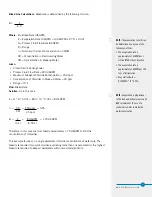
Page 33: ...SGPM x R F x 0 001 Q Process Fluid Flow Rate USGPM R Range n Number of Cycles of Concentration CR CM CR Concentration in Recirculating Water CM Concentration in Make up Water Given Closed Circuit Cooling Tower Process Fluid Flow Rate 800 USGPM Maximum Allowable Chloride Concentration 250 ppm Concentration of Chlorides in Make up Water 45 ppm Range 10 F Find Bleed Rate Solution So in this case E Q ...

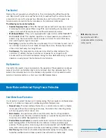
Page 34: ...an control and dry operation The method of control employed on a given application depends upon the climatic extremes which are expected the variations in heat load that will be encountered and the compatibility of the control system with other portions of the installation In subfreezing ambient temperatures effective icing control may require a combination of these three methods Operate each unit...

Page 35: ...n visually inspect the fan blades for ice formation Dry Operation One method to prevent icing is dry operation Dry operation of the evaporative condenser protects fans from ice formation due to mist and splash from the cold water basin The water in the cold water basin must be drained in dry operation For dry operation switch points and recommendations contact your local BAC representative Basin W...

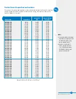
Page 36: ...the fluid leaving the coil is not less than 50 F 10 C For FXV FXV3 Closed Circuit Cooling Towers with glycol as the heat transfer liquid maintain a minimum heat load so that the temperature of the glycol leaving the coil is not less than 45 F 7 2 C PFi To maintain the leaving fluid temperature at 50 F 10 C when the process load is extremely light or shut off apply an auxiliary heat load to the cir...

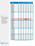
Page 37: ...0809x 24T FXV 0809x 30T FXV 0809x 36T FXV 0809x 16Q FXV 0809x 24Q FXV 0809x 32Q 118 700 141 500 163 000 203 100 222 000 239 900 256 800 205 300 233 900 260 400 143 600 207 500 246 200 60 400 59 800 59 200 79 300 78 600 77 900 77 300 80 700 79 800 79 100 61 200 82 000 81 300 47 400 46 900 46 400 60 200 59 600 59 100 58 600 61 200 60 500 60 000 48 000 62 200 61 600 FXV 0812x 12D FXV 0812x 16D FXV 08...

Page 38: ...FXV 1218x 36H 331 900 404 200 471 100 567 700 625 000 678 200 728 000 586 700 677 600 760 500 416 900 593 400 716 100 789 300 109 000 106 400 103 900 137 800 134 900 132 300 129 800 145 800 143 000 140 400 112 200 148 700 145 700 150 100 97 000 94 600 92 500 115 600 113 200 110 900 108 800 122 300 119 900 117 700 99 800 124 700 122 200 125 900 FXV3 1224 20D XX FXV3 1224 24D XX FXV3 1224 24T XX FXV...

Page 39: ...l solution If the coil is not protected an automatic drain valve and vacuum breaker are recommended to drain the coil if flow stops or the fluid temperature drops below 50 F 10 C when the ambient temperature is below freezing Further protection against coil freeze up is possible with the installation of an alarm to alert personnel when the temperature of the fluid leaving the coil falls below 50ºF...

Page 40: ...evel control can only be used with the supplied combination temperature water level sensor probe Please contact your local BAC Representative for replacement parts Stand Alone BAC Heater Control Panel Optional The heater control system consists of a heater control panel and a combination temperature water level sensor The stainless steel sensor probe with 1 2 NPT mounting fitting has an on off rel...

Page 41: ...the heater control panel cover Energize the system and listen for the contactor closing Operate the system until the ice is melted around the probe After operation de energize the circuit disconnect the heater control panel and tag out the circuit Remove the jumper check all connections replace the cover and place the system back in service WARNING Dangerous voltages are present in this equipment ...

Page 42: ...bration A light adjacent to the set point control comes on the instant the measured vibration level exceeds the set point The unit can be periodically calibrated on line by turning the set point control down until the light comes on This setting is then compared with the vibration measured with a portable vibration meter thus providing a calibration check of the unit If the trip setting is maintai...

Page 43: ...ncy drives VFDs for fan motor control must use inverter duty motors built in compliance with NEMA standard MG 1 Part 31 Operation of the unit at a speed which resonates with components of the drive system or support structure may result in vibrations which could damage the components or structure and or create objectionable noise Therefore these resonant speed ranges should be identified at start ...

Page 44: ... provided by others Be sure to route and fasten the wire so that it will not contact any rotating parts inside the unit when the drive system is operational Get out of the unit and ensure that the drive system is all clear Remove the lockout from the motor circuit With the VFD off record the vibration level indicated on the vibration analyzer and confirm that it is very low only picking up ambient...

Page 45: ...as peaked and continues to fall record the speed where the value equals 0 35 ips as the upper end of the lockout range Using this data a baseline for vibration history can be developed The vibration levels can be monitored yearly and the trend used to indicate potential wear or the need to replace components in the drive system After the entire speed range has been checked and any resonances ident...

Page 46: ...el backing ring gasket to the inside of the cold water basin 6 Position the flange to the outside of the cold water basin 7 Bolt the flange and the stainless steel backing plate together using stainless steel bolts 8 Seal any exposed galvanized steel of the connection inside the cold water basin with Vulkem Caulk as shown in Figure 13 Supplies Provided by BAC Recommended Supplies Provided by Other...

Page 47: ...OWERS ICE THERMAL STORAGE EVAPORATIVE CONDENSERS HYBRID PRODUCTS PARTS SERVICES w w w B a l t i m o r e A i r c o i l c o m 7600 Dorsey Run Road Jessup MD 20794 Telephone 410 799 6200 Fax 410 799 6416 2020 Baltimore Aircoil Company M248 3 B ...

Reviews: