34
Operation
Considerations for
Accessories
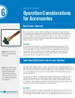
Basin Heater
Operation
Electronic Vibration Cutout
Switch
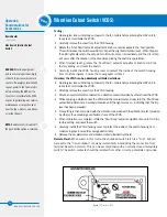
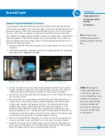
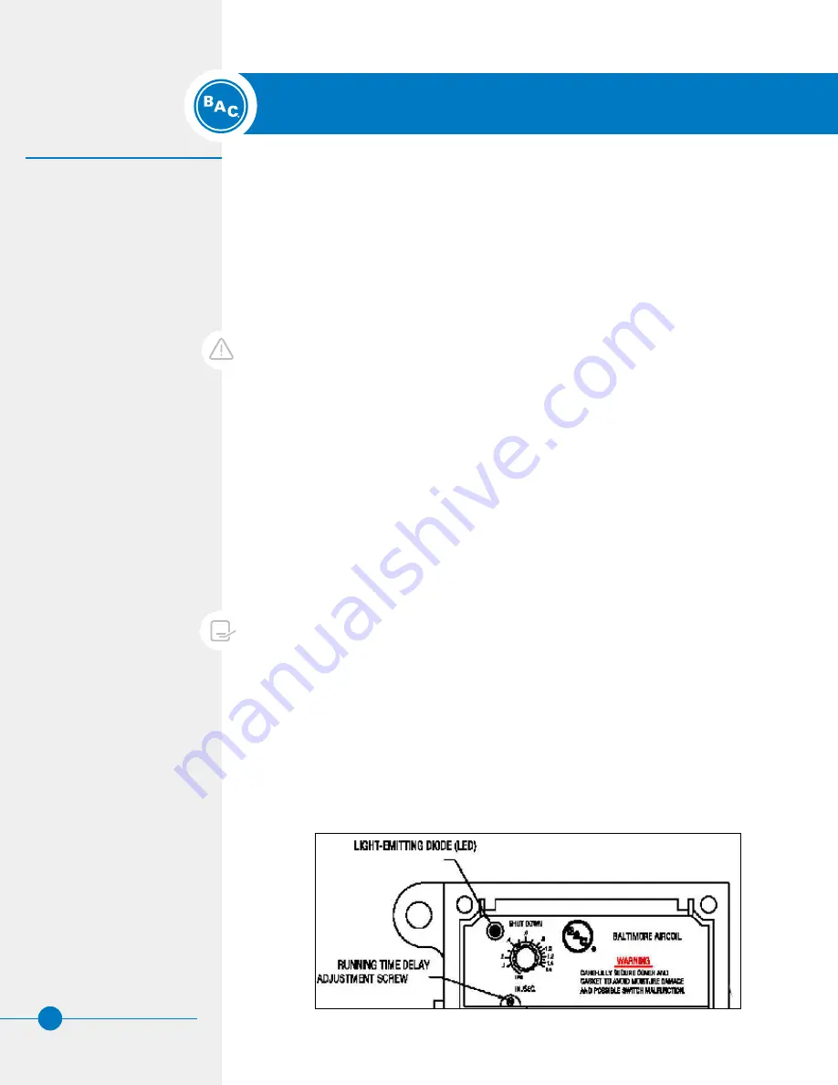
Figure 11.
Electronic VCOS
DANGER:
Rotating equipment
will cause severe personal injury
or death to persons who come in
contact. De-energize, lock out and
tag out power to the fan motor(s)
before entering the HXV unit to
reset, test, or calibrate the VCOS,
or prior to performing any service,
maintenance or inspection on or
near the fans, motors, and drives,
or inside the unit
NOTE:
Remote reset is disabled if
the push button option is selected.
Vibration Cutout Switch (VCOS)
Testing:
• De-energize, lock out and tag out power to the fan motors before entering the HXV unit to
reset, test, or calibrate the VCOS.
• Carefully remove the cover from the VCOS housing.
• Rotate the ‘Shut Down’ setpoint adjustment knob counterclockwise to the ‘Test’ position.
This will increase the switch sensitivity to trip at the slightest vibration level. When tripped,
the LED light adjacent to the set point control will come on immediately, and the circuit trip
will occur after the duration of the time delay, proving the switch is operational.
• When finished testing, rotate the ‘Shut Down’ setpoint adjustment knob to 0.45 ips
factory setting, and reset the switch.
• Carefully install the VCOS housing cover to protect the inside of the switch housing
from moisture ingress. Ensure the cover gasket is intact.
If desired, the VCOS can be periodically calibrated as follows:
• De-energize, lock out and tag out power to the fan motors before entering the HXV unit to
reset, test, or calibrate the VCOS.
• Carefully remove the cover from the VCOS housing.
• Mount an accelerometer connected to a vibration meter (provided by others) near the VCOS.
• While applying a vibration near the VCOS and the accelerometer, slowly turn the ‘Shut Down’
setpoint adjustment knob counterclockwise until the light comes on, indicating that the trip
level has been exceeded.
• This setting is then compared with the vibration measured with the vibration meter (provided
by others), thus providing a calibration check of the VCOS.
• When calibration is completed, rotate the ‘Shut Down’ setpoint adjustment knob to 0.45 ips
factory setting, and reset the switch.
• Carefully install the VCOS housing cover to protect the inside of the switch housing from
moisture ingress. Ensure the cover gasket is intact.
• Remove the accelerometer and vibration meter (provided by others).
Remote Reset:
When wired in this mode, the shutdown switch latch is a “trip”, but can
be reset to the “non-shutdown” mode by momentarily interrupting the connection from
terminal Reset to Common. This can be accomplished with a normally closed momentary
switch. The switch contacts should be isolated from other circuits, potentials or grounds.


