38
• As stated previously, when adjusting the VFD speed, proceed slowly while monitoring
the vibration levels. If the vibration value approaches 0.35 ips (0-peak), slowly “zero
in” on the speed where the value equals 0.35 ips, and record the speed at which this
occurs as the lower end of the lockout range. Also record the vibration level at this
speed.
• Continue to slowly increase the speed while monitoring the vibration level. If this is a
resonance, then the value should peak and eventually decrease to a level that is below
0.35 ips as the speed is increased. After the vibration level has peaked and continues
to fall, record the speed where the value equals 0.35 ips as the upper end of the
lockout range.
• Using this data, a baseline for vibration history can be developed. The vibration levels
can be monitored yearly and the trend used to indicate potential wear or the need to
replace components in the drive system.
• After the entire speed range has been checked and any resonances identified, ensure
the VFD that controls the fan motor is then turned off, and the power to the motor
circuit is locked out.
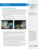
• Enter the unit, and carefully remove the accelerometer, along with any associated
wiring from the unit.
• Work with the VFD contractor to enter the lockout speed ranges, if any have been
identified, into the VFD, so the unit will not operate at a resonant speed.
• Once it has been verified that the drive system is all clear, return the unit to its normal
operating condition.
• Keep a record of any lockout speed ranges for future reference.

